Three-clamping lock
A lock and lock housing technology, applied in the direction of connecting components, mechanical equipment, friction clamping detachable fasteners, etc., can solve the problems of low connection strength, manufacturing structure, complicated process, and loose lock heads, etc., to achieve Guarantee strength and fastness, reduce production cost and improve work efficiency
- Summary
- Abstract
- Description
- Claims
- Application Information
AI Technical Summary
Problems solved by technology
Method used
Image
Examples
Embodiment 1
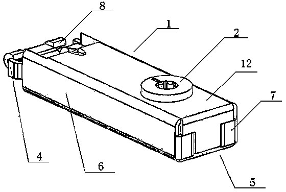
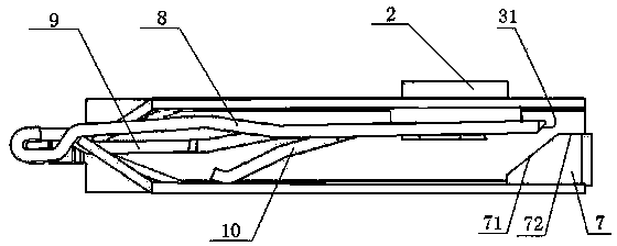
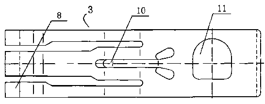
[0023] Embodiment 1: see attached figure 1 with attached figure 2 , the present invention proposes a three-clip lock, which is used to build a support connection in a trade fair or store structure assembly system, including a lock case 1, a three-clip reed 3, an eccentric wheel 2 and a rear cover, and the three-clip reed The sheet 3 is arranged in the lock case 1, and a hole matched with the eccentric wheel 2 is arranged on the three-catch reed sheet 3, and the three-clip reed sheet 3 moves forward and backward by the rotation of the eccentric wheel 2 arranged in the hole, and the The lock case 1 is formed by stamping a seamless steel pipe with a rectangular cross-section, and the rear cover is formed by bending the side plates 6 and the upper panel 12 at the rear end of the lock case; specifically, the side plates 6 at the rear end of the lock case are respectively The left and right support plates 7 that support the three clip reeds are formed by two inward bendings of 18...
Embodiment 2
[0026] Embodiment 2: see attached Figure 4 with attached Figure 5 , the three-clip lock involved in this embodiment includes a lock case 1, a three-catch reed 3, an eccentric wheel 2 and a rear cover 5. The lock case 1 is stamped from a seamless steel pipe with a rectangular cross section, and the rear cover The upper part of the inner side is provided with an upper support 14, and the lower part is provided with a lower support 13. The upper edge of the upper support 14 and the lower edge of the lower support 13 are closely matched with the inner wall of the lock housing to realize the tight connection between the back cover 5 and the lock housing. A gap 16 for the front and rear movement of the three-clip reeds is formed between them for the support after the three-clip reeds 3 enter; 3. The protruding direction is positive and inclined downward, and the rear end surface of the three clip reeds is an inclined surface 31 and matches with the front inclined surface 15 of th...
Embodiment 3
[0027] Embodiment 3: see attached Image 6 with attached Figure 7 , the three-clip lock involved in this embodiment, part of the structure has been improved on the basis of Embodiment 3: the rear cover is directly formed by one-time bending of the lower panel 17, and the lower support 18 is an independent component, which is fixed by screws 181 on the inside of the back cover; if Figure 8 As shown: the three-catch reed 3 involved in this embodiment is in the middle of its three lock tongues, and the middle lock tongue 9 and the two side lock tongues 8 are respectively bent to form an upward protrusion 91 and a downward protrusion 81; corresponding At the rearward position of the middle lock tongue protrusion, an inclined bearing surface 191 is formed by stamping on the upper panel of the lock housing; There are three inclined bearing surfaces 19, and the front ends of the three inclined bearing surfaces respectively act on the raised upper inclined surfaces of the three de...
PUM
 Abstract
Description
Claims
Application Information
 - R&D
- Intellectual Property
- Life Sciences
- Materials
- Tech Scout
- Unparalleled Data Quality
- Higher Quality Content
- 60% Fewer Hallucinations
Browse by: Latest US Patents, China's latest patents, Technical Efficacy Thesaurus, Application Domain, Technology Topic, Popular Technical Reports.
© 2025 PatSnap. All rights reserved.Legal|Privacy policy|Modern Slavery Act Transparency Statement|Sitemap|About US| Contact US: help@patsnap.com


