Rotating joint, loading arm with rotating joint and loading equipment with loading arm

A technology for rotary joints and loading and unloading equipment, which is applied to equipment loaded into pressure vessels, equipment discharged from pressure vessels, mechanical equipment, etc., can solve problems such as inability to load and unload compressed natural gas, achieve improved rotational performance and flexibility, and is not easy The effect of aging, easy maintenance and disassembly

Active Publication Date: 2014-01-01
鞍山市昱虎流体设备有限公司
View PDF5 Cites 9 Cited by
  • Summary
  • Abstract
  • Description
  • Claims
  • Application Information

AI Technical Summary

Problems solved by technology

[0005] Aiming at the problem in the prior art that compressed natural gas can only be loaded and unloaded through hoses, and pipelines made of steel pipes cannot be loaded and unloaded due to structural defects in the rotary joint, no effective solution has been proposed so far. Therefore, the present invention The main purpose is to provide a rotary joint, a loading and unloading arm including the rotary joint, and a loading and unloading device including the loading and unloading arm, so as to solve the above problems

Method used


Image

  • Rotating joint, loading arm with rotating joint and loading equipment with loading arm
  • Rotating joint, loading arm with rotating joint and loading equipment with loading arm
  • Rotating joint, loading arm with rotating joint and loading equipment with loading arm

Examples


specific Embodiment approach 2

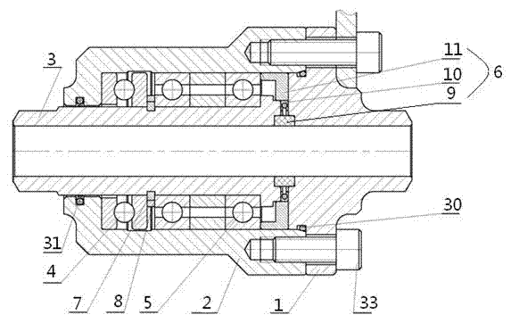
[0036] Specific implementation mode two, such as figure 2 As shown, wherein, the rotary joint 12 may include a flange gland 1, a housing 2, and a rotating core 3. One end of the housing 2 is connected to the flange gland 1, and the other end is connected to the rotating core 3 placed in its cavity. A thrust bearing 4 and three radial bearings 5 ​​are installed between the rotating core 3 and the housing 2; a double-channel sealing device 6 is arranged between the rotating core 3 and the opposite end faces of the flange gland 1 .

specific Embodiment approach 3

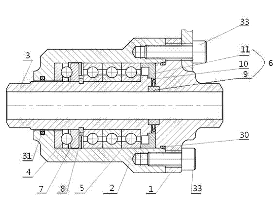
[0037] Specific implementation mode three, such as image 3 As shown, wherein, the rotary joint 12 may also include a flange gland 1, a housing 2, and a rotating core 3. One end of the housing 2 is connected to the flange gland 1, and the other end is connected to the rotating core placed in its cavity. 3 connection, two radial bearings 5 ​​are installed between the rotating core 3 and the housing 2, and an inner support sleeve and an outer support sleeve are arranged in the middle of the two radial bearings 5; the rotating core 3 and the method A double-channel sealing device 6 is arranged between the opposite end faces of the flange gland 1 .

specific Embodiment approach 4

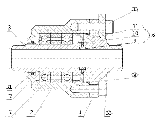
[0038] Specific implementation mode four, such as Figure 4 As shown, wherein, the rotary joint 12 may also include a flange gland 1, a housing 2, and a rotating core 3. One end of the housing 2 is connected to the flange gland 1, and the other end is connected to the rotating core placed in its cavity. 3 connection, three radial bearings 5 ​​are installed between the rotating core 3 and the housing 2; a double-channel sealing device 6 is arranged between the rotating core 3 and the opposite end faces of the flange gland 1.


PUM


Abstract

The invention discloses a rotating joint, a loading arm with the rotating joint and loading equipment with the loading arm. A plurality of radial bearings (5) and/or thrust bearings (4) are installed between a rotating core (3) of the rotating joint (12) and a shell (2). The rotating joint (12) is arranged at the lower end of an inner revolving arm (13) of the loading arm. One end of an outer revolving pipeline (16) is connected with the inner revolving arm (13) through a rotating unit (15). A bearing (24) of the loading equipment is connected with a three-way joint (20) through a shaft (29). A rapid joint (25) is connected with a movable pipeline (17). The loading equipment can be rotated at will in the vertical direction and the horizontal direction through the rotating joint (12) and the rotating unit (15) formed by the rotating joint (12), the rapid joint (25) can be flexibly adjusted to the needed loading position, and the loading equipment is high in pressure resistance, safe, reliable and long in service life.

Description

technical field [0001] The invention relates to the field of loading and unloading equipment, in particular to a rotary joint, a loading and unloading arm including the rotary joint, and loading and unloading equipment including the loading and unloading arm. Background technique [0002] With the rapid development of my country's economy, natural gas has been recognized by more and more people as a new type of clean energy. There are more and more cities using natural gas as the main energy source, and more and more cars using natural gas as energy. , the amount of compressed natural gas and the number of filling stations are increasing, and the loading and unloading devices for compressed natural gas are also increasing. Since the pressure of compressed natural gas is as high as 25MPa, there is a risk of rupture and explosion of storage containers and pipelines. At the same time, it is also a flammable and explosive product, which has the risk of combustion and explosion. ...

Claims


Application Information

Patent Timeline
Patent Type & Authority Applications(China)
IPC IPC(8): F16L27/08F17C5/06F17C7/00
CPCF16L27/0828F16L27/0832F17C5/06F17C7/00
Inventor 张胜虎李国超王德元刘叔伦李忠彦张鹏
Owner 鞍山市昱虎流体设备有限公司
Why Eureka
Try Eureka