
Liquid nitrogen tank

A liquid nitrogen tank and tank body technology, applied in the field of liquid nitrogen tanks, can solve the problems of liquid nitrogen tank waste, difficult to cover in time, and unsolved problems such as liquid nitrogen tanks, and achieve the effect of convenient use, reasonable structure, and reduced leakage

Inactive Publication Date: 2014-01-01
常熟市董浜镇徐市盛峰液压配件厂
View PDF5 Cites 0 Cited by
  • Summary
  • Abstract
  • Description
  • Claims
  • Application Information

AI Technical Summary

Problems solved by technology

[0002] Using liquid nitrogen to freeze cells and sperm is a commonly used technology in the research fields of medicine and biology. The convenient use of liquid nitrogen tanks is a major factor to ensure research. The application number is 201120286876.9. It solves the problem that it is difficult for medical staff to cover the liquid nitrogen tank in time during the cryotherapy process, which causes waste. The double-covered liquid nitrogen tank includes a tank body, an outer cover, a nitrogen taking spoon, and an inner cover. There is a stop on the inner wall of the mouth, and the periphery of the inner cover is stuck on the stop on the inner wall of the mouth of the tank; the handle of the nitrogen-taking spoon passes through the inner cover and is fixed with the inner cover. The present invention has the advantages of convenient use, good sealing performance and It can effectively avoid the advantages of liquid nitrogen volatilization and waste, but it does not solve the problems of difficult storage and retrieval in liquid nitrogen tanks and reduce the loss of liquid nitrogen

Method used


Image

  • Liquid nitrogen tank

Examples


Embodiment Construction

[0011] In order to make the technical means, creative features, goals and effects achieved by the present invention easy to understand, the present invention will be further described below in conjunction with specific embodiments.

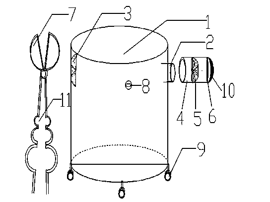
[0012] Such as figure 1 As shown, a liquid nitrogen tank includes a tank body 1, a tank mouth 2 is provided on the top of the side wall of the tank body 1, a lighting area 3 is also provided on the side wall of the tank body 1, and a tank mouth 2 is provided on the side wall of the tank body 1. There is a tank cover 4, and the tank cover 4 includes a special glass cover 5 and a sealing cover 6. The design of the lighting area and the special glass cover helps to strengthen the lighting. After opening the sealing cover, you can first find the desired object outside the tank position, and then open the special glass cover to take the required items, which is convenient to reduce the loss of liquid nitrogen. The outside of the tank body 1 is provide...


PUM


Abstract

The invention discloses a liquid nitrogen tank and relates to the field of hydraulic equipment. The liquid nitrogen tank comprises a tank body, wherein a tank opening is arranged at the top end of the side wall of the tank body; the side wall of the tank body is also provided with a daylighting area; the tank opening is provided with a tank cover; the tank cover comprises a special glass cover and a sealing cover; due to design of the daylighting area and the special glass cover, the daylighting effect is enhanced; after the sealing cover is opened, the position of a needed object can be firstly found outside the tank, and then the special glass cover is opened for taking the needed object, so that the reduction of the loss of liquid nitrogen is convenient; a long-handle semicircular clamp is arranged outside the tank body, and the object contained in a cylindrical container can be clamped in and out, so that the freezing of liquid nitrogen is reduced; a liquid-nitrogen suspending ball is arranged in the tank body, so that the amount of the liquid nitrogen can be observed at any time and the liquid nitrogen can be filled in time; universal wheels are arranged at the opposite sides of a tank opening at the bottom part of the tank body, so that the liquid nitrogen tank can be pushed and moved; and simultaneously, the universal wheels and the tank opening exist relatively, and when the liquid nitrogen tank is moved, the liquid nitrogen is separated from the tank opening, so that the leakage is reduced.

Description

technical field [0001] The invention relates to the field of hydraulic equipment, in particular to a liquid nitrogen tank. Background technique [0002] Using liquid nitrogen to freeze cells and sperm is a commonly used technology in the research fields of medicine and biology. The convenient use of liquid nitrogen tanks is a major factor to ensure research. The application number is 201120286876.9. It solves the problem that it is difficult for medical staff to cover the liquid nitrogen tank in time during the cryotherapy process, which causes waste. The double-covered liquid nitrogen tank includes a tank body, an outer cover, a nitrogen taking spoon, and an inner cover. There is a stop on the inner wall of the mouth, and the periphery of the inner cover is stuck on the stop on the inner wall of the mouth of the tank; the handle of the nitrogen-taking spoon passes through the inner cover and is fixed with the inner cover. The present invention has the advantages of conv...

Claims


Application Information

Patent Timeline
Patent Type & Authority Applications(China)
IPC IPC(8): F17C1/00F17C13/02F17C13/06
Inventor 盛建青
Owner 常熟市董浜镇徐市盛峰液压配件厂
Learn More