
Light emitting device and lighting device including the light emitting device

A technology of light-emitting device and light-emitting direction, applied in the field of lighting device and light-emitting device, can solve the problems of chromaticity change and chromatic aberration adjustment being difficult to achieve as desired, and difficult to finely adjust the mixing ratio of blue light and yellow light, etc.

Inactive Publication Date: 2017-09-15
OSRAM GMBH
View PDF4 Cites 0 Cited by
  • Summary
  • Abstract
  • Description
  • Claims
  • Application Information

AI Technical Summary

Problems solved by technology

Therefore, although it is attempted to adjust the mixing ratio of blue light and yellow light emitted in different directions by adjusting the thickness of the phosphor cover 44, it is difficult to finely adjust the blue and yellow light emission directions due to changes in thickness. The mixing ratio of blue light and yellow light emitted in the direction
Therefore, the effect of this solution on the adjustment of color difference is not satisfactory
Moreover, this chromatic aberration is also difficult to eliminate by further adjusting the thickness of the phosphor cover 44, because, while adjusting the thickness to eliminate the chromatic aberration, the direction of the light path is also changed, so that the chromaticity of the light emitted from various directions change again

Method used


Image

  • Light emitting device and lighting device including the light emitting device
  • Light emitting device and lighting device including the light emitting device
  • Light emitting device and lighting device including the light emitting device

Examples


Embodiment Construction

[0034] In the following detailed description, reference is made to the accompanying drawings which form a part hereof, and in which are shown by way of illustrations specific embodiments in which the invention may be practiced. With respect to the figures, directional terms such as "top", "bottom", "front", "rear", "upper", "lower", etc. are used with reference to the orientation of the figures being described. Since components of embodiments of the present invention may be placed in many different orientations, the terminology of orientation is used for illustration only and not in any limiting sense. It is to be understood that other embodiments may be utilized and structural or logical changes may be made without departing from the scope of the present invention. Therefore, the following detailed description should not be taken in a limiting sense, and the invention is defined by the appended claims.

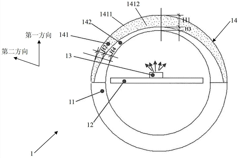
[0035] figure 1 A cross-sectional view of a light emitting device 1 a...


PUM


Abstract

The present invention provides a light-emitting device and a lighting device comprising the light-emitting device. The light-emitting device includes: a substrate; a light source disposed on the substrate; a cover part spaced from the light source by a certain distance, and transmitting the light emitted by the light source to the outside, It is characterized in that the cover part includes: a first part, which converts the wavelength of a part of the light emitted by the light source, and has different thicknesses in at least two different light emitting directions of the light source; a second part, which has different thicknesses in the two different light emitting directions have a different thickness to compensate for the thickness of the first part.

Description

technical field [0001] The present invention relates to a light emitting device and an illuminating device including the light emitting device, more particularly, to a light emitting device with uniform chromaticity and an illuminating device including the light emitting device. Background technique [0002] According to its internal structure or packaging form, light sources such as LEDs usually have a certain spatial distribution of luminous intensity. For example, figure 2 An example of a luminous intensity spatial distribution curve (light distribution curve) of an LED chip is shown. Such as figure 2 As shown, in the normal direction of the light-emitting surface of the LED chip (0-degree direction), the light intensity has a maximum value, and as the light-emitting angle increases, the light intensity gradually decreases, and has a minimum value in the 90-degree direction. [0003] Figure 3A to Figure 3C An example in which the LED chip is applied to a light emitti...

Claims


Application Information

Patent Timeline
Patent Type & Authority Patents(China)
IPC IPC(8): F21K9/27F21V9/10F21Y115/10F21V9/40
CPCH01L33/508F21K9/64
Inventor 何源源冯耀军明玉生王华
Owner OSRAM GMBH
Learn More