Structure and method for packaging pressure sensor

A pressure sensor and packaging structure technology, applied in the measurement of the force of the piezoelectric device, fluid pressure measurement using the piezoelectric device, etc., can solve the problems of cumbersome steps, poor air tightness and reliability, and high production costs. Achieve the effect of simple process steps, high reliability and low production cost

Active Publication Date: 2014-01-01
NAT CENT FOR ADVANCED PACKAGING
View PDF7 Cites 36 Cited by
  • Summary
  • Abstract
  • Description
  • Claims
  • Application Information

AI Technical Summary

Problems solved by technology

[0006] In order to solve the problems of cumbersome steps in the packaging process of the existing pressure sensor, poor airtightness and reliability of the package, and high production costs, the present invention provides a package structure of the pressure sensor, including: an upper cover plate, a lower cover plate and a belt A pressure sensor chip with a vibrating film; the lower cover plate is provided with a first rectangular groove and a second rectangular groove; the second rectangular groove is embedded in the bottom of the first rectangular groove, so that the The first rectangular groove and the second rectangular groove are connected to form a two-stage cavity structure; the bottom of the first rectangular groove is provided with a through hole through the lower cover plate, which is connected with the bump of the pressure sensor chip; the through hole The upper and lower surfaces of the hole are connected to the pad and the wiring layer; the bumps of the pressure sensor chip are connected to the through holes, so that the pressure sensor chip is embedded in the first rectangular groove and is hermetically connected to the first rectangular groove ; The upper cover is provided with a third rectangular groove, the center of the bottom of the third rectangular groove is provided with a through hole through the upper cover; the pressure sensor chip is located between the upper cover and the Inside the space formed by the connection of the lower cover

Method used


Image

  • Structure and method for packaging pressure sensor
  • Structure and method for packaging pressure sensor
  • Structure and method for packaging pressure sensor

Examples


Embodiment Construction

[0035] The technical solutions of the present invention will be further described below in conjunction with the accompanying drawings and embodiments.

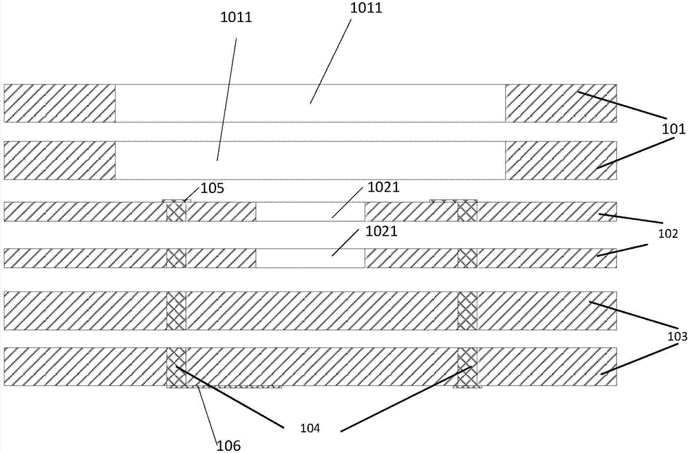
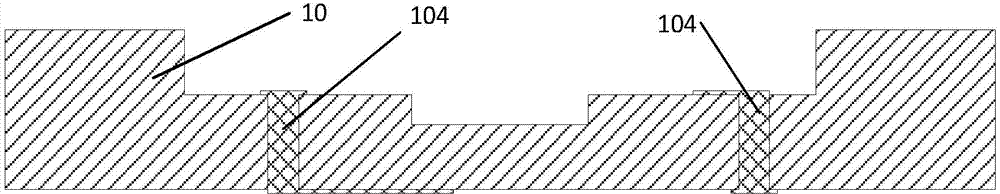
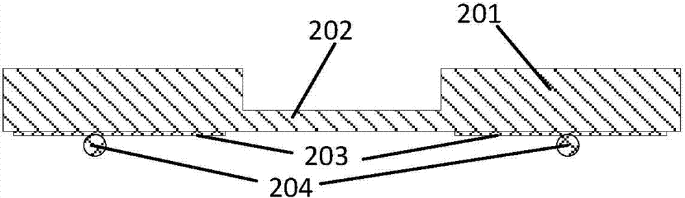
[0036] see figure 2 , 3 , 6 and 7, the embodiment of the present invention provides a packaging structure of a pressure sensor, including: an upper cover 40, a lower cover 10, a pressure sensor chip 201 with a vibrating membrane; the lower cover 10 is provided with a first The rectangular groove 1011 and the second rectangular groove 1021; the second rectangular groove 1021 is embedded in the bottom of the first rectangular groove 1011, so that the first rectangular groove 1011 and the second rectangular groove 1021 are connected to form a two-stage cavity structure The bottom of the first rectangular groove 1011 is provided with a through hole 104 through the lower cover plate 10; the upper and lower surfaces of the through hole 104 are connected with the pad 105 and the wiring layer 106; the pressure sensor chip bump 204 i...


PUM


Abstract

The invention discloses a structure and method for packaging a pressure sensor, and belongs to the technical field of microelectronic packaging. The structure for packaging the pressure sensor comprises an upper cover board, a lower cover board and a pressure sensor chip. The lower cover board is provided with a first rectangular groove and a second rectangular groove. The bottom of the first rectangular groove is embedded in the second rectangular groove so that the first rectangular groove and the second rectangular groove can be communicated to form a two-stage cavity structure. Through holes penetrating through the lower cover board are formed in the bottom of the first rectangular groove. The upper surfaces and the lower surfaces of the through holes are connected with a bonding pad and a wiring layer respectively. Protrusions of the pressure sensor chip are connected with the through holes of the lower cover board. The upper cover board is provided with a third rectangular groove. The pressure sensor chip is located inside a space formed by connecting the upper cover board and the lower cover board. The invention further discloses the method for packaging the pressure sensor. By means of the system and method for packaging the pressure sensor, the capacity for resisting a severe environment, stress uniformity, the reliability and the accuracy of the pressure sensor chip are improved, and application demands of special environments with high temperature, high humidity and the like can be met.

Description

technical field [0001] The invention relates to the technical field of microelectronic packaging, in particular to a packaging structure and method of a pressure sensor. Background technique [0002] Pressure sensors are widely used in many fields such as industrial production, medical and health care, environmental monitoring, and scientific research. The basic principle is to convert pressure changes into changes in electrical signals. Using pressure sensors to integrate the acquisition, processing and execution of pressure change information to form a multi-functional composite micro-intelligent system can not only reduce the cost of the entire electromechanical system, but also complete tasks that cannot be completed by large-scale electromechanical systems; In addition, pressure sensors can also be embedded in large-scale systems, thereby greatly improving the automation, intelligence and reliability of the system. Pressure sensor is the miniaturization achievement of ...

Claims


Application Information

Patent Timeline
Patent Type & Authority Applications(China)
IPC IPC(8): G01L1/16G01L9/08
Inventor 周云燕宋见王启东曹立强万里兮
Owner NAT CENT FOR ADVANCED PACKAGING
Why Eureka
Try Eureka