
Low-voltage and high-current rotating test rig

A rotating test, high current technology, applied in circuit breaker testing and other directions, can solve the problems of inconvenient handling, high cost of double-layer turntable, difficult maintenance of power supply equipment, etc., to prevent inadvertent operation, shorten time spent, tripping The effect of time convenience

Inactive Publication Date: 2014-01-01
SHANGHAI ELECTRICAL APPLIANCES RES INSTGROUP +1
View PDF5 Cites 2 Cited by
  • Summary
  • Abstract
  • Description
  • Claims
  • Application Information

AI Technical Summary

Problems solved by technology

Since the test product should be placed on the turntable, and the low-voltage and high-current power supply is obtained from the power supply device through the thick and flexible connecting wire, the turntable needs to be turned 360°, and the thick and flexible wiring is bound to be entangled, which is easy to short circuit, which will inevitably bring the test product How to place large-sized power supply equipment when rotating
The current main solutions are: 1) judge the maximum disturbance surface of the test product through experience, and directly test the maximum radiation disturbance surface towards the antenna, that is, the test product and the power supply equipment are fixed on the turntable without rotation. Disadvantages: only It is difficult to simulate the actual situation based on experience; 2) The test product and the power supply equipment are placed on the turntable at the same time, and the reflection effect caused by the power supply equipment is ignored, and the rotation test is carried out. The test data is inaccurate due to electromagnetic wave reflection; 3) The test product is placed on the turntable, the power supply equipment is placed outside the turntable, the soft connection part is extended as far as possible, and the turntable is rotated as much as possible under the premise of ensuring that the soft connection line is not entangled. : The thick and soft wiring needs to be very long, and it is unrealistic to avoid intertwining when the turntable is reversing; 4) Using a double-layer turntable scheme, the test product is placed on the first turntable, and the power supply equipment is placed on the second turntable. Carry out the rotation test together, this plan is a rare arrangement that fully meets the standard test requirements, but the cost of the double-layer turntable is very high, and the maintenance of the power supply equipment is extremely difficult. At present, there is no such successful plan in China

Method used


Image

  • Low-voltage and high-current rotating test rig
  • Low-voltage and high-current rotating test rig
  • Low-voltage and high-current rotating test rig

Examples


Embodiment

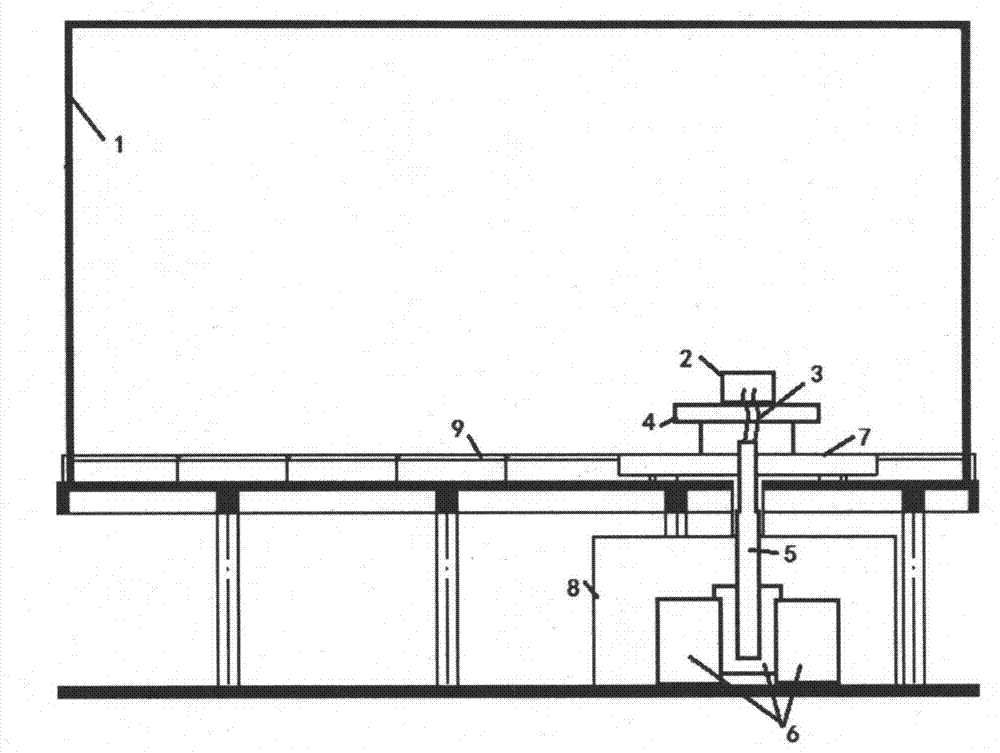
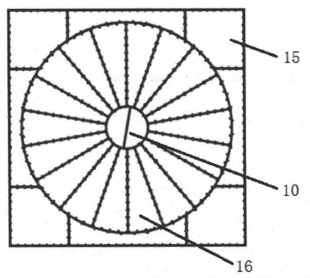
[0030] Such as figure 2 Shown is a schematic diagram of the structure of a low-voltage, high-current rotary test device. The low-voltage, high-current rotary test device includes an anechoic chamber 1, and the anechoic chamber 1 is provided with a grounding plate 9 and a turntable 7 embedded in the grounding plate 9. The turntable 7 is located at On one side of the anechoic chamber 1, an insulation test table 4 is provided on the turntable 7, and the test object 2 is set on the insulation test table 4. The center of the turntable 7 is provided with a center hole 10 of the turntable, and a copper bar 5 is provided in the center hole 10 of the turntable. One end of the copper bar 5 is connected to the power supply end of the low-voltage high-current power supply device 6 , and the other end is connected to the tested product 2 through the flexible connection wire 3 . The shield room 8 is located underground. The flexible connecting wire 3 is a copper braid.

[0031] Such as ...


PUM


Abstract

The invention provides a low-voltage and high-current rotating test rig which is characterized by comprising an anechoic chamber; a rotary table is arranged in the anechoic chamber, an insulation test table is arranged on the rotary table, and an object to be tested is arranged on the insulation test table; a rotary table central hole is formed in the center of the rotary table, a copper bar is arranged in the rotary table central hole, one end of the copper bar is connected with a power supply end of a power supply device, and the other end of the copper bar is connected with the object to be tested through a soft connecting line; the power supply device is arranged in a screened room. According to the low-voltage and high-current rotating test rig, the low-voltage and high-current power supply device is placed below the rotary table and is connected with the object to be tested in a manner that the copper bar can be controlled to ascend or descend at an air shaft area of the rotary table, and the rotary table can rotate by 180 degrees in the forward direction and reverse direction to fully meet the substantial requirements for a maximum radiation harassment surface of the object to be tested for radiation emission test assessment. Meanwhile, the overall manufacturing cost of the customized central air shaft rotary table and the copper bar is far lower than the manufacturing cost of a double-layer rotary table, so the low-voltage and high-current rotating test rig has a great advantage on the manufacturing cost, and the power supply device is quite convenient to maintain.

Description

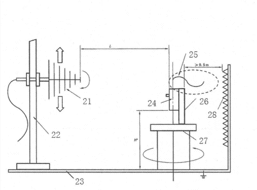
technical field [0001] The invention relates to a low-voltage high-current rotating test device, which is used for radiation emission testing of low-voltage circuit breakers. Background technique [0002] The latest standards for the radiation emission test of universal circuit breakers are the national standard GB14048.2-2008 "Low-voltage switchgear and control equipment Part 2: Circuit breakers" and the international standard IEC60947-2:2006+A1:2009 "Low-voltageswitchgearandcontrolgear- Clause F.5.4 of Part2: Circuit-breakers. Standard requirements, when radiating radio frequency disturbance (30MHz ~ 1GHz), should be based on figure 1 Set up the test. [0003] Most testing agencies do not fully meet the standard requirements when conducting radiation emission tests on universal circuit breakers. Since the test product should be placed on the turntable, and the low-voltage and high-current power supply is obtained from the power supply device through the thick and flexib...

Claims


Application Information

Patent Timeline
Patent Type & Authority Applications(China)
IPC IPC(8): G01R31/327
Inventor 叶琼瑜刘媛宋江伟袁书传郑军奇
Owner SHANGHAI ELECTRICAL APPLIANCES RES INSTGROUP
Learn More