Polarized structure and liquid crystal display

A liquid crystal display and polarizing technology, which is applied in optics, instruments, diffraction gratings, etc., can solve the problems of polarizer deformation, light leakage, and affecting the picture quality of liquid crystal displays, and achieve the effects of shortening time, saving polarizing materials, and increasing picture quality

Inactive Publication Date: 2014-01-01
NANJING CEC PANDA LCD TECH
View PDF5 Cites 22 Cited by
  • Summary
  • Abstract
  • Description
  • Claims
  • Application Information

AI Technical Summary

Problems solved by technology

[0002] At present, polarizers are generally made of multi-layer polymer film materials. However, polymer film materials are easily affected by the environment and cause deformation of the polarizer. However, there is no better material that can replace polymer film materials to make polarizers. , so in the prior art, polarizers are generally used in liquid crystal displays, such as figure 1 As shown, in the existing liquid crystal display, the polarizer 1 is pasted on the outside of the color filter substrate 2 and the thin film field effect transistor substrate 3 respectively, but due to the polarizer material will cause the deformation of the polarizer due to the ambient temperature, which will affect the liquid crystal. The picture quality displayed by the monitor may cause light leakage and other phenomena

Method used


Image

  • Polarized structure and liquid crystal display
  • Polarized structure and liquid crystal display
  • Polarized structure and liquid crystal display

Examples


Embodiment Construction

[0019] The technical solutions of the present invention will be described in detail below, but the protection scope of the present invention is not limited to the embodiments.

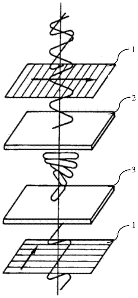
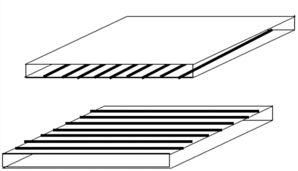
[0020] Such as figure 2 The polarizing structure shown includes two transparent glass plates parallel to each other, and a metal grating layer is respectively arranged on the inner surfaces of the two transparent glass plates, and the metal grating layer includes a plurality of metal lines parallel to each other, wherein the two transparent glass plates The axial angles of the metal wires on the plates differ by 90°, wherein the axial angle of the upper transparent glass plate is 90°, and the axial angle of the lower transparent glass plate is 0°. The metal wire can be chrome wire, silver wire or aluminum wire. When the electromagnetic wave passes through the polarizing structure, it is polarized, that is, when the electromagnetic wave passes through the metal grating layer, the light in one directio...


PUM


Abstract

The invention discloses a polarized structure. The polarized structure comprises two transparent glass boards which are parallel, wherein a metal grating layer is arranged on the inner surface of each transparent glass board, each metal grating layer comprises a plurality of metal lines which are parallel, and the axial included angle of 90 degrees is formed between the metal lines on the two transparent glass boards. The invention further provides a liquid crystal display with the polarized structure. A transparent substrate provided with the metal grating layers formed by the metal lines which are parallel replaces an existing polarized board to achieve the polarization function, and the problem that the existing polarized board is prone to deforming due to environment temperature is solved effectively; the liquid crystal display with the polarized structure not only saves polarized materials, removes the procedure for pasting the polarized board and effectively shortens the time of the whole procedure, but also effectively solves the problem of light leakage caused by deformation of the polarized board, and increases quality of pictures.

Description

technical field [0001] The invention relates to a polarizing structure and a liquid crystal display adopting the structure. Background technique [0002] At present, polarizers are generally made of multi-layer polymer film materials. However, polymer film materials are easily affected by the environment and cause deformation of the polarizer. However, there is no better material that can replace polymer film materials to make polarizers. , so in the prior art, polarizers are generally used in liquid crystal displays, such as figure 1 As shown, in the existing liquid crystal display, the polarizer 1 is pasted on the outside of the color filter substrate 2 and the thin film field effect transistor substrate 3 respectively, but due to the polarizer material will cause the deformation of the polarizer due to the ambient temperature, which will affect the liquid crystal. The picture quality displayed by the monitor may cause light leakage and other phenomena. Contents of the ...

Claims


Application Information

Patent Timeline
Patent Type & Authority Applications(China)
IPC IPC(8): G02F1/1335G02F1/1362G02B5/18G02B5/30
Inventor 林佳玲
Owner NANJING CEC PANDA LCD TECH
Why Eureka
Try Eureka