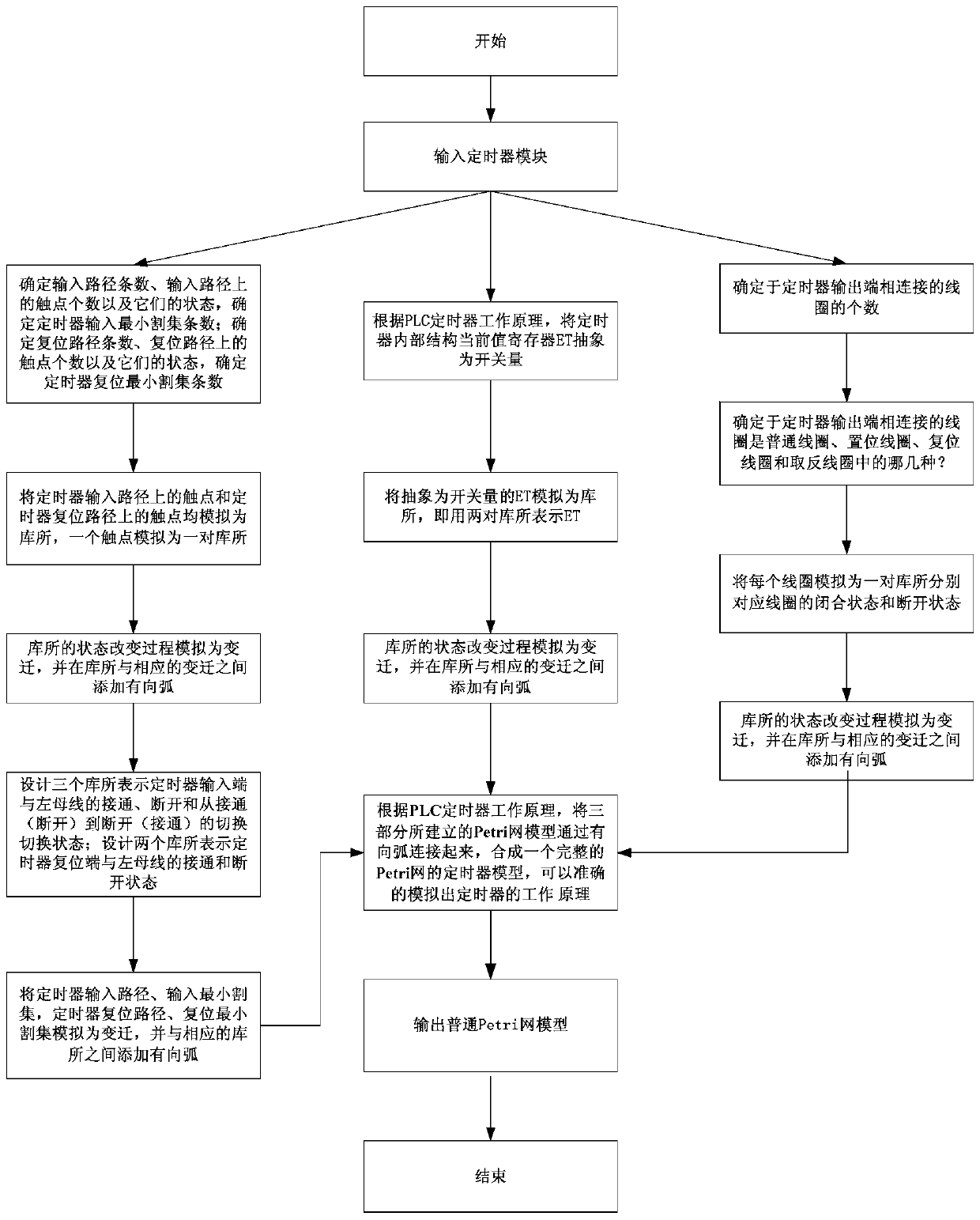
A method of converting plc timer module into common petri net
A technology of module conversion and timer, which is applied in the program control and electrical program control of sequence/logic controllers, and can solve problems such as high development costs, train collisions, and heavy workload
- Summary
- Abstract
- Description
- Claims
- Application Information
AI Technical Summary
Problems solved by technology
Method used
Image
Examples
Embodiment 1
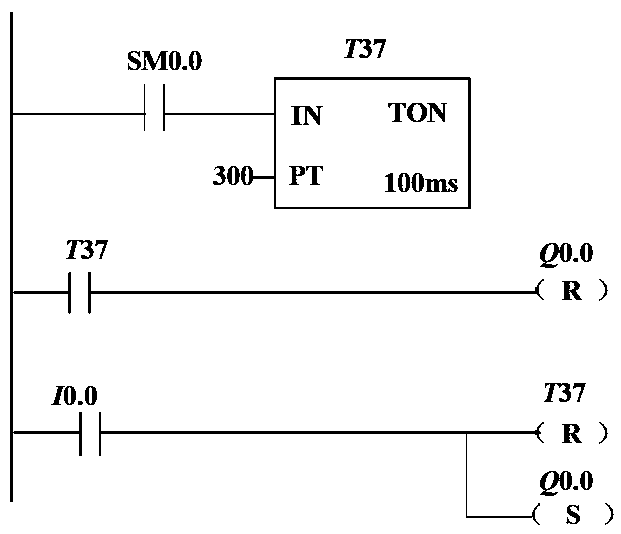
[0248] Embodiment 1: Timing lighting of ladder lights
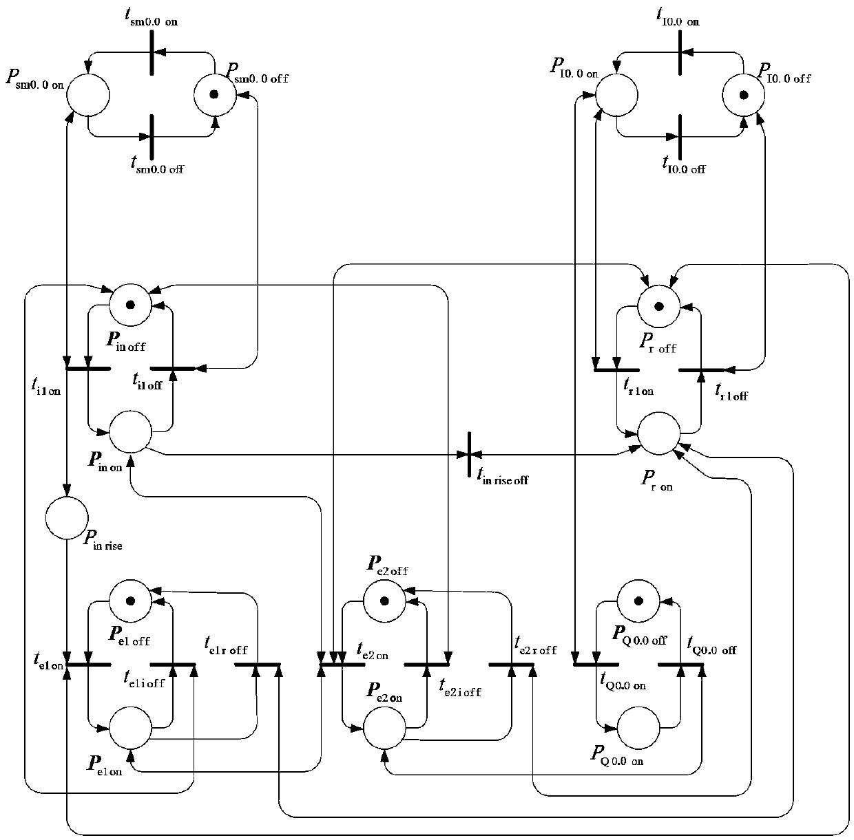
[0249] The present embodiment 1 is used to light the step lamp. The ON buttons on the different layers are connected to the control input I0.0. When the ON button of I0.0 is pressed, the light at the output terminal Q0.0 will glow for 30s. If the ON button is pressed again during this period, the time interval has to start from the beginning again. This will ensure that the last time you press the ON button, the light will not go out within 30s. Such as figure 2 Shown is the PLC ladder diagram written according to the control requirements. SM0.0 is RUN monitoring, when PLC is in RUN state, SM0.0 is always 1. If the ON button is pressed, the ON signal of the input I0.0 is valid (I0.0=1), the timer T37 is reset, and the timer T37 starts counting from the beginning. At the same time, the output Q0.0 coil is set (lights on). When the timer T37 counts for 30s, the timer is turned on, and the output Q0.0 will be off agai...
Embodiment 2
[0267] Example 2. The program for delaying the disconnection of the motor
[0268] When the power is disconnected, the motor does not stop rotating immediately, but keeps running for 5 seconds before stopping. Such as Figure 4 Shown is the PLC ladder diagram written according to the control requirements. I0.0 is the power switch, I0.1 is the control switch of the motor, I1.0 is the reset button, and Q1.0 is the output. When the power switch I0.0 and the motor switch I0.1 are both on, Q1.0 is on, and the motor starts to rotate; when the motor switch I0.1 is off or the power switch I0.0 is off, the timer T38 starts, 5s After the timing time is up, the motor stops running. Whenever, as long as the reset button I1.0 is on, the timer T38 will be reset immediately, the output Q1.0 will be false, the motor will stop running, and the timer will be cleared at the same time.
[0269] In the following, the timer T38 in Embodiment 2 is transformed into a common Petri net model.
[0...
Embodiment 3
[0286] Embodiment 3. The program of the running time of the signal lights at the crossroads
[0287] This example selects a small part of the program for the operation control of the traffic lights at the intersection. When the start button is pressed, the timer T40 starts, the output is true, the north-south direction is green light, and the east-west direction is red light, and the time is 30s. Such as Figure 6 Shown is the PLC ladder diagram written according to the control requirements. I0.0 is the start button, I1.0 is the reset button, M1.0 is the intermediate relay, Q1.0 and Q1.1 represent the output. When the start button I0.0 is turned on, the timer T40 starts, and the output is true. Q1.0 is true, indicating that the north-south direction is a green light, and Q1.1 is true, indicating that the east-west direction is a red light. When the 30s timer expires, the timer disconnected, the output is false.
[0288] Signal lights at intersections are generally divided ...
PUM
 Abstract
Description
Claims
Application Information
 - R&D
- Intellectual Property
- Life Sciences
- Materials
- Tech Scout
- Unparalleled Data Quality
- Higher Quality Content
- 60% Fewer Hallucinations
Browse by: Latest US Patents, China's latest patents, Technical Efficacy Thesaurus, Application Domain, Technology Topic, Popular Technical Reports.
© 2025 PatSnap. All rights reserved.Legal|Privacy policy|Modern Slavery Act Transparency Statement|Sitemap|About US| Contact US: help@patsnap.com


