Network interconnecting device for cache-free optical interconnection networks

A technology of network interconnection and optical interconnection, which is applied in the field of network interconnection devices, can solve the problems of waste of resources and unused microrings, and achieve the effect of reducing optical loss, the number of microrings and optical loss are obvious, and the reduction is obvious

Inactive Publication Date: 2014-01-01
NAT UNIV OF DEFENSE TECH
View PDF2 Cites 4 Cited by
  • Summary
  • Abstract
  • Description
  • Claims
  • Application Information

AI Technical Summary

Problems solved by technology

However, in BOIN networks, due to the actual topology, there are situations where microrings are not utilized, which leads to waste of resources

Method used


Image

  • Network interconnecting device for cache-free optical interconnection networks
  • Network interconnecting device for cache-free optical interconnection networks
  • Network interconnecting device for cache-free optical interconnection networks

Examples


Embodiment Construction

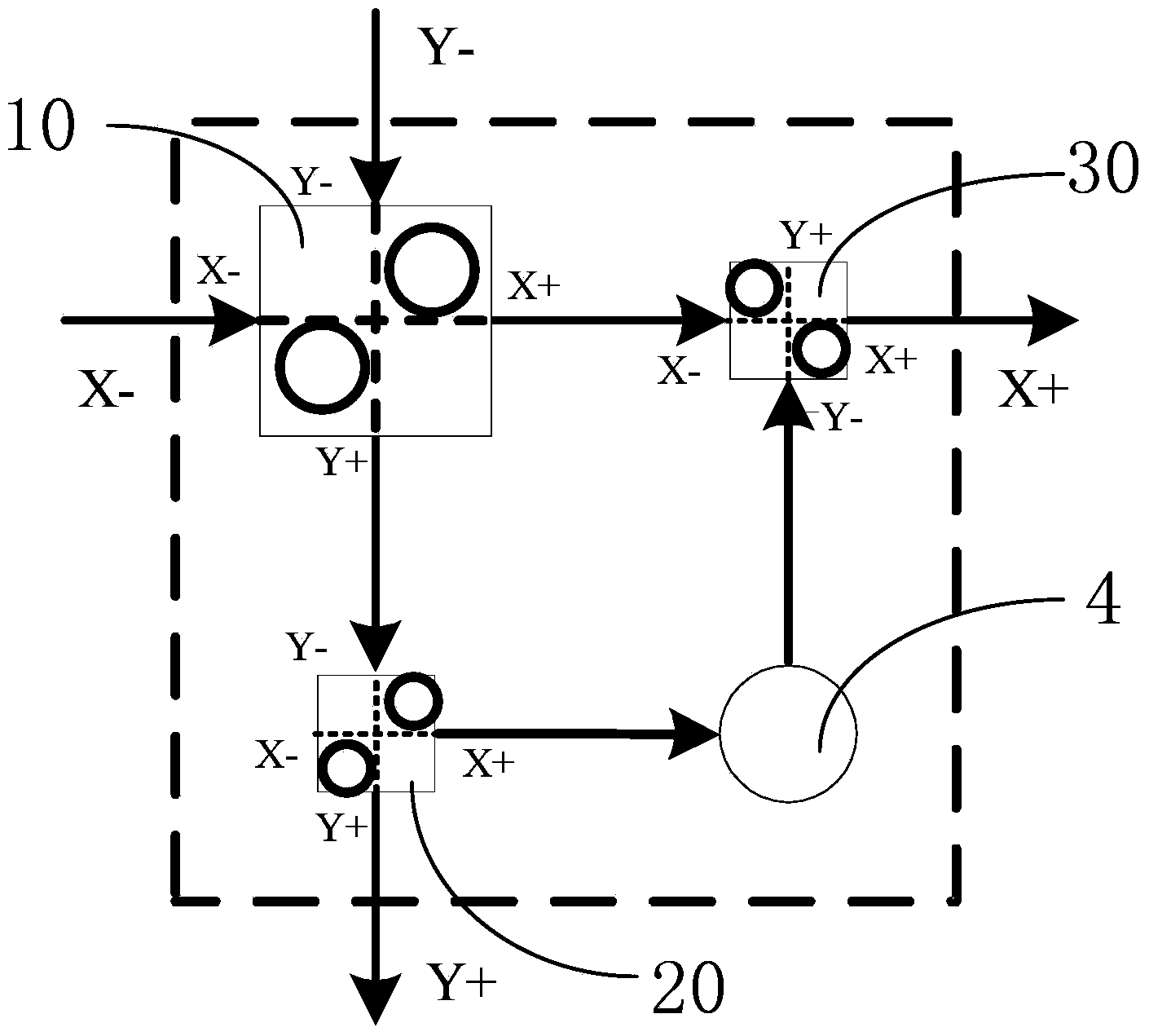
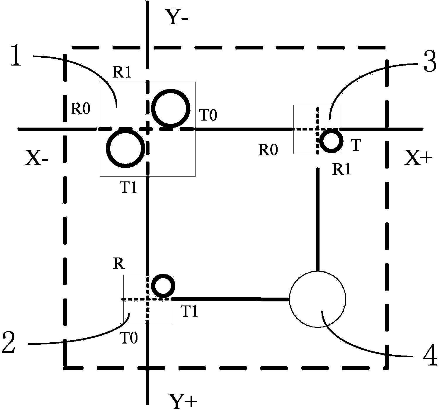
[0024] Such as figure 2 As shown, the network interconnection device for the bufferless optical interconnection network in this embodiment includes an electrical control network node and an optical data network node, the electrical control network node includes a processing unit with a photoelectric conversion circuit, and the optical data network node includes a Frequency 2×2 Optical Switching Unit 1 (referred to as PSE2×2), 1×2 Optical Switching Unit 2 (referred to as PSE1×2) and 2×1 Optical Switching Unit 3 (referred to as PSE2×1), the above three Photonic Switch Elements are connected through optical waveguides.

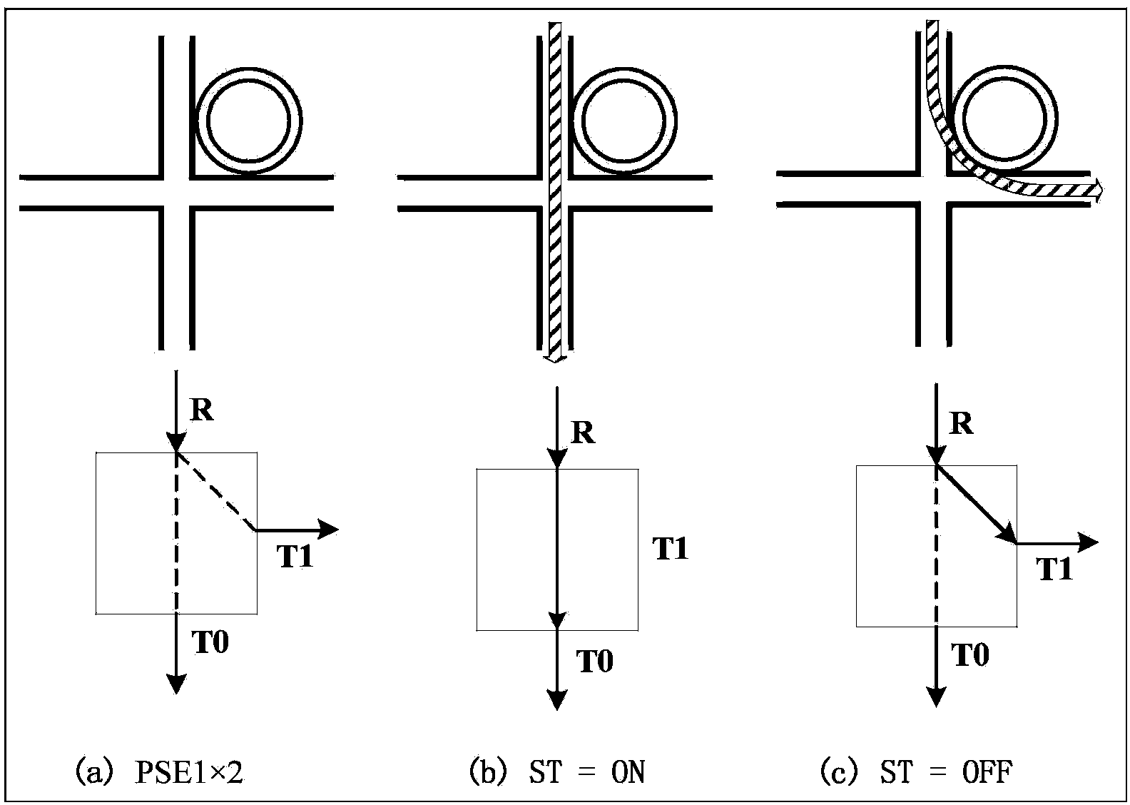
[0025] Such as image 3As shown, the PSE1×2 of this embodiment is realized by a ring resonator structure. PSE1×2 is composed of two intersecting optical waveguides and a microring. The two optical waveguides of PSE1×2 are vertically intersecting each other, and PSE1 The ×2 microring circumscribes two waveguides and is located between the input port R and the s...


PUM


Abstract

The invention discloses a network interconnecting device for cache-free optical interconnection networks. The device comprises an electric controlling network node and an optical data network node. The electric controlling network node comprises a processing unit, and the optical data network node comprises a 2*2 optical switching unit, a 1*2 optical switching unit and a 2*1 optical switching unit, wherein the 2*2 optical switching unit comprises two micro rings, the 1*2 optical switching unit and the 2*1 optical switching unit respectively include one micro ring, the two input ends of the 2*2 optical switching unit are connected with an X- input port and a Y- input port respectively, one output end of the 1*2 optical switching unit is connected with a Y+ output port, the other output end of the 1*2 optical switching unit is connected with a processing unit through a photoelectric conversion circuit, the other input end of the 2*1 optical switching unit is connected with the output end of the processing unit, and the output end of the 2*1 optical switching unit is connected with an X+ output port. The network interconnecting device has the advantages of being small in micro ring quantity, little in optical loss and simple in structure.

Description

technical field [0001] The invention relates to the field of optical interconnection networks, in particular to a network interconnection device for non-buffer optical interconnection networks. Background technique [0002] In a traditional electrical interconnection network, the power consumption generated by message transmission, buffering and switching grows quadratically with the increase of data transmission rate. Therefore, the interconnection network based on electrical interconnection has been difficult to meet the communication requirements of high-performance computers. In the optical interconnection network, light waves are used as information carriers, which have the advantages of low power consumption, high interconnection density, and low transmission delay. Optical interconnection network has been widely accepted as an effective method to improve the bandwidth bottleneck of communication system, and it opens up a new way for the design of interconnection netw...

Claims


Application Information

Patent Timeline
Patent Type & Authority Applications(China)
IPC IPC(8): H04B10/27
Inventor 窦强窦文华彭超任双印鲁佳李宝亮周乐文韩岗钱悦郭龙飞苏醒任斌叶进覃晨
Owner NAT UNIV OF DEFENSE TECH
Why Eureka
Try Eureka