Planar three-freedom-degree parallel mechanism driven by three linear drivers and application thereof

A linear drive, linear drive technology, applied in the direction of manipulators, program-controlled manipulators, manufacturing tools, etc., can solve the problems affecting the normal and smooth operation of the overall equipment, uneven distribution of driving force, and easy entanglement of movements, so as to ensure normal and smooth operation. , conducive to even distribution, the effect of less invalid load

Inactive Publication Date: 2014-01-08
XINXIANG UNIV
View PDF7 Cites 13 Cited by
  • Summary
  • Abstract
  • Description
  • Claims
  • Application Information

AI Technical Summary

Problems solved by technology

[0002] At present, the stir-frying mechanism, vibrating screen, vibrating test bench, transmission mechanism, parallel robot and other mechanisms of the automatic cooking machine are usually driven by a cross slide or an in-plane three-degree-of-freedom mechanism. Due to structural limitations, the existing driving mechanism There are the following defects in use: 1. The driving force is unevenly distributed and the output stability is poor, which affects the normal and stable operation of the overall equipment; 2. The wires and pipelines need to move with the driving mechanism, so the pipelines are not only long in length, but also in It is easy to be entangled with each other during movement, and a pipeline moving device must be added to prevent the equipment from stopping due to pipeline entanglement
3. The structure is complex and there are many parts. The weight of the motor, slide rail, fixed structure and other parts of the upper system will be used as the load of the lower system. There are many invalid loads and low efficiency.

Method used


Image

  • Planar three-freedom-degree parallel mechanism driven by three linear drivers and application thereof
  • Planar three-freedom-degree parallel mechanism driven by three linear drivers and application thereof
  • Planar three-freedom-degree parallel mechanism driven by three linear drivers and application thereof

Examples


Embodiment Construction

[0021] The embodiments of the present invention will be described in detail below in conjunction with the accompanying drawings; it should be noted that the embodiments are illustrative, not restrictive, and cannot limit the protection scope of the present invention.

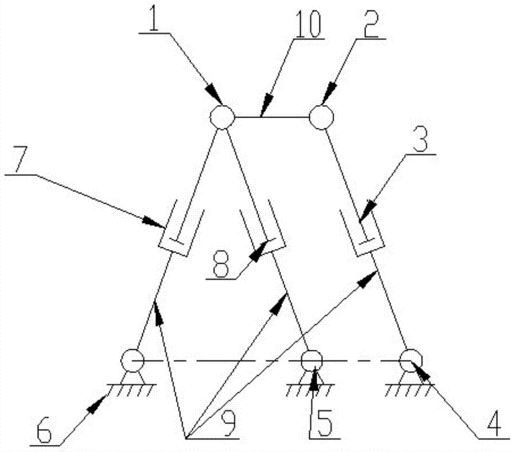
[0022] A planar three-degree-of-freedom parallel mechanism with three linear drives, including three linear drives 3, 7, 8 and five hinges, two of which are upper hinges 1, 2, and three hinges are lower hinges 4, 5, 6 , the three lower hinges are all fixed on the ground or the equipment frame, and the axes of the three lower hinges are located on the same axis.

[0023] Each lower hinge is connected to a linear driver, and its specific structure is: each lower hinge is hinged with a lower link 9, and each lower link is connected to the lower end of the respective linear driver. The linear drive is a linear cylinder or a hydraulic cylinder or an electric push rod or an electric cylinder or other linear drive devi...


PUM


Abstract

The invention relates to a planar three-freedom-degree parallel mechanism driven by three linear drivers. The planar three-freedom-degree parallel mechanism comprises the three linear drivers and five hinges, wherein two of the five hinges are upper hinges, the other three hinges are lower hinges, the three lower hinges are all fixed to the ground or a device rack, the lower hinges are connected with the linear drivers respectively, the upper ends of the two linear drivers with the lower ends connected with the lower hinges on the outer sides are connected with the upper hinges on the same sides respectively, the upper end of the linear driver with the lower end connected with the middle lower hinge is connected with the upper hinge on any side, and the two upper hinges are connected with each other through an output connecting rod. The parallel mechanism is used as a stir-fry mechanism of an automatic cooker or a vibrating screen or a vibration test table or a transmission mechanism or a parallel robot. The planar three-freedom-degree parallel mechanism driven by the three linear drivers is reasonable in design, ingenious in structure, convenient to install, easy to obtain and wide in application range, and when the parallel mechanism is used, even distribution of driving force can be ensured, stable output can be ensured and the structure of the whole device can be simplified.

Description

technical field [0001] The invention relates to the field of connecting rod drive mechanisms, in particular to a plane three-degree-of-freedom parallel mechanism driven by three straight lines and its application. Background technique [0002] At present, the stir-frying mechanism, vibrating screen, vibrating test bench, transmission mechanism, parallel robot and other mechanisms of the automatic cooking machine are usually driven by a cross slide or an in-plane three-degree-of-freedom mechanism. Due to structural limitations, the existing driving mechanism There are the following defects in use: 1. The driving force is unevenly distributed and the output stability is poor, which affects the normal and stable operation of the overall equipment; 2. The wires and pipelines need to move with the driving mechanism, so the pipelines are not only long in length, but also in It is easy to be entangled with each other during movement, and a pipeline moving device must be added to pr...

Claims


Application Information

Patent Timeline
Patent Type & Authority Applications(China)
IPC IPC(8): B25J9/02B25J9/10
Inventor 孙志超
Owner XINXIANG UNIV
Why Eureka
Try Eureka