[0036] The present invention will now be further described in detail with reference to the accompanying drawings and embodiments. These drawings are simplified schematic diagrams, which only illustrate the basic structure of the present invention in a schematic manner, and therefore only show the structures related to the present invention.
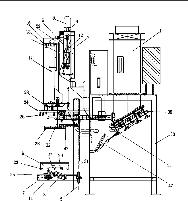
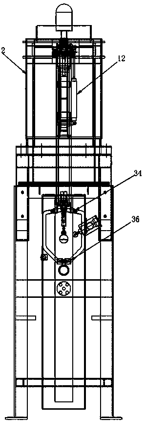
[0037] Such as Figure 1-5 As shown, a packaging machine that automatically takes bags, loads, and transfers includes a frame arranged in a vertical direction, a barrel 1 arranged on the frame, and a discharge nozzle 42 connected to the outlet of the barrel 1. The axis of the cylinder 1 is in the vertical direction, and the axis of the discharge nozzle 42 extends transversely. The packaging machine also includes a manipulator device arranged above the discharge nozzle 42 and a receiving device arranged below the discharge nozzle 42.
[0038] Specifically, the rack includes a support frame 2. The discharging nozzle 42 may include a main nozzle with a larger caliber and a sub-nozzle with a smaller caliber arranged parallel to the main nozzle, which is convenient for controlling the discharging accuracy. The manipulator device includes a driving device, and also includes a rod-shaped mechanical arm arranged on the support frame 2 and connected with the driving device. One end of the mechanical arm is a connecting end 22, and the other end is a free end. The mechanical arm is rotatably arranged on the support frame 2 around the connecting end 22, and the free end is provided with a suction cup. The driving device includes a first driving device capable of driving the mechanical arm to rotate around the connecting end 22, and a second driving device capable of driving the suction cup to move closer to and away from the free end along the extending direction of the mechanical arm. The mechanical arm that can rotate around one end is easy to adjust to the angular position of the packaging bag in the vertical plane, and it can be used with suction cups that can be close to and away from the mechanical arm to achieve multi-angle adjustment.
[0039] The support frame 2 is installed vertically above the discharge nozzle 42, and the top end is provided with a laterally extending fixed plate 4, and a first rotating shaft 6 extending vertically downward is provided on the fixed plate 4, the first rotating shaft 6 can rotate around its own central axis, The driving device further includes a third driving device that drives the first rotating shaft 6 to rotate, and the third driving device may be a motor 8. The connecting end 22 of the mechanical arm is axially connected to the first rotating shaft 6. The first driving device is a first air cylinder 12, and the first air cylinder 12 includes a cylinder and a piston capable of telescoping relative to the cylinder. One end of the first cylinder 12 in the telescopic direction is axially connected to the arm connecting end 22, and the other end is fixed. For example, the outer end of the piston of the first cylinder 12 is axially connected with the connecting end 22, and the outer end of the cylinder is fixed on the side wall of the first rotating shaft 6. When the motor 8 drives the first rotating shaft 6 to rotate, the mechanical arm arranged on the first rotating shaft 6 rotates synchronously in the transverse plane. The movement of the first cylinder 12 drives the mechanical arm to rotate in a vertical plane around its connecting end 22. Since the entire mechanical arm is set on the first rotating shaft 6 and can follow the first rotating shaft 6 to rotate, it is convenient to further adjust the angular position of the suction cup on the mechanical arm in the horizontal plane, further increasing the manipulator adjustment angle and the reachable range, which is convenient for more accurate The capture of packaging bags in different positions. It is especially suitable for transporting packaging bags to the discharge nozzle 42.
[0040] The second driving device is a second cylinder 14, and the second cylinder 14 also includes a cylinder and a piston capable of telescoping relative to the cylinder. One end of the second cylinder 14 in the telescopic direction is fixed to the mechanical arm, and the other end is connected with a suction cup. That is, the second cylinder 14 connects the connecting end 22 and the free end of the mechanical arm. For example, the outer end of the piston of the second cylinder 14 is connected to the suction cup, and the outer end of the cylinder is fixed to the connecting end 22 of the robot arm through the fixing seat 16 on the cylinder; the robot arm is also provided with a guide cylinder 18 arranged parallel to the second cylinder 14 to guide The cylinder 18 also includes a cylinder and a piston capable of telescoping relative to the cylinder. One end of the guide cylinder 18 in the telescopic direction is fixed to the mechanical arm, and the other end is also connected to a suction cup. For example, the outer end of the piston of the guiding cylinder 18 is connected with the suction cup, and the outer end of the cylinder is also fixed to the connecting end 22 of the mechanical arm through the fixing seat 16 on the cylinder. The connecting end 22 of the mechanical arm is elongated, and its extending direction forms an angle γ, 90° with the axial direction of the second cylinder 14 <180°. Both the first driving device and the second driving device use air cylinders, which can stably control the movement of the mechanical arm. In particular, the guide cylinder 18 provided on one side of the second cylinder 14 can better limit the movement direction of the suction cup relative to the mechanical arm, and increase the smoothness of the movement of the suction cup.
[0041] The suction cup includes a disc-shaped body 24 and a number of vacuum suction cups 26 arranged at the lower end of the body 24. The outer end of the piston of the second cylinder 14 and the outer end of the piston of the guiding cylinder 18 are both fixed to the main body 24 of the suction cup through the lower cylinder fixing seat 28. The vacuum suction cups 26 are distributed on the side of the main body 24 facing away from the second cylinder 14, and the vacuum suction cups 26 can be circumferentially distributed on the main body 24, which facilitates increasing the suction area and more stable suction of the packaging bag.
[0042] The manipulator device further includes a mechanical claw 32 provided at the free end of the manipulator arm. The mechanical claw 32 includes two C-shaped fingers 34 each having one end coaxially connected to the mechanical arm, and a third air cylinder capable of driving the two fingers 34 to open and close. The axis of the finger 34 connected to one end of the robot arm is parallel to the axis of the first rotating shaft 6 at the connecting end 22 of the robot arm, and the other end is provided with a clamping strip 38 extending parallel to its axis direction, which is convenient for enlarging and clamping the package. The contact area of the bag. The free ends of the two fingers 34 are respectively provided with rubber pads 36. When clamping the packaging bag, it can increase the friction and reduce the damage to the packaging bag. The two fingers 34 of the mechanical claw 32 are respectively located on the two axial sides of the discharge nozzle 42 during filling, and are clamped from both sides to stabilize the packaging bag being filled.
[0043] The frame includes a vertically extending bracket. The receiving device includes a bearing plate and a driving cylinder 3 arranged on the bracket. The bearing plate is rotatably arranged on the bracket. One end of the driving cylinder 3 in the telescopic direction is fixed to the bracket, and the other end is connected to the bearing. Board shaft connection.
[0044] The bracket includes a vertical column 5 and a horizontal plate-shaped support 7. The upper end of the column 5 is fixed with a discharging nozzle 42 extending laterally. The receiving plate is arranged on the support 7. The receiving plate includes a transversely extending plate-shaped body 9 and a connecting piece connecting the body 9 and the support 7. One end of the connecting piece is fixed to the body 9, and the other end is axially connected to the support 7 through a second rotating shaft 11, and the second rotating shaft 11 is longitudinally connected. The axial direction of the driving cylinder 3 is perpendicular to the second rotating shaft 11. The main body 9 includes two tapping plates respectively arranged at the upper ends of the second rotating shaft 11. The tapping plate includes an inclined portion 13 at an obtuse angle to the lateral plane where the second rotating shaft 11 is located, and also includes a lower end of the inclined portion 13 and the second rotating shaft. 11 is a vertical portion 15 where the horizontal plane is at right angles. The inclined portion 13 of the splitter plate, on the one hand, has the effect of concentrating and condensing the material to be received in the middle, and on the other hand, it has a certain buffer effect on the weight of the material that increases in the receiving direction. The angle of the obtuse angle α is preferably 170°-175°, which can realize a relatively stable receiving of materials and a better cushioning. The main body 9 is connected to the support 7 through two parallel connecting pieces, and the two tap plates are respectively fixed to the corresponding connecting pieces through vertical portions 15. Furthermore, a rib 17 is provided on the top of the inclined portion 13 to protect the packaged materials from overturning to the side. The angle β between the rib 17 and the transverse plane where the second rotating shaft 11 is located is preferably 95°-100°. The tapping board 9 includes two layers of elastic plate bodies 19, and a hollow buffer cavity 21 is formed between the two layers of elastic plate bodies 19, which can strengthen the buffer effect and prolong the service life.
[0045] The vertical portion 15 of the main body 9 is provided with a plurality of first fixing holes 23 along the transverse direction, and the connecting member is fixed to the main body 9 through the first fixing holes 23. The connecting piece can select different positions of the first fixing holes 23 to be connected to the body 9, so as to adjust the installation position and the force position of the body 9 according to the position where the material falls. The connecting piece includes an elongated rotating piece 25. One end of the rotating piece 25 is axially connected to the support 7 and the other end is vertically provided with an elongated connecting piece 27, which is fixed to the main body 9 by the connecting piece 27. Specifically, the connecting piece 27 is provided with a plurality of second fixing holes 29 arranged in a straight line, and the spacing of the second fixing holes 29 is adapted to the spacing of the first fixing holes 23 on the body 9, and the number of the first fixing holes 23 is more than The second fixing hole 29 is convenient for adjusting the position of the main body 9. The connecting piece 27 is threadedly connected to the corresponding first fixing hole 23 on the body 9 through all the second fixing holes 29. The connecting piece 27 is fixed to the body at 9 positions, and the connection is more stable.
[0046] The column 5 is provided with a plurality of mounting holes 31 arranged in a vertical direction, and the support 7 is screwed to the column 5 through the mounting holes 31. The number of mounting holes 31 is more than two, and the mounting height of the receiving plate can be changed by selecting mounting holes 31 of different heights. This adjustable form is convenient to adjust the height of the receiving plate according to the specific blanking height and the height difference between the receiving plate and the conveying equipment, so as to achieve the most stable and safe receiving and transferring effect.
[0047] The packaging machine of the present invention also includes a bag-holding structure arranged on the periphery of the discharge nozzle 42. The frame also includes a main body 33 extending vertically, the support frame 2 is fixed on the main body 33, and the bracket is provided with a side portion of the main body 33. The bag holding structure includes a bag holding plate 37 arranged on the main body 33, a clamping plate 39 fixed on the main body 33 and arranged opposite to the bag holding plate 37, and a fourth driving device that drives the bag holding plate 37 close to and away from the clamping plate 39 .
[0048] Specifically, the main body 33 is provided with an inclined plate-shaped mounting frame 35, and the bag-holding plate 37 is arranged on the mounting frame 35 in parallel. The mounting frame 35 and the clamping plate 39 are fixed by a connecting piece 41. Preferably, the included angle between the plane of the bagging plate 37 and the horizontal plane is 30°-45°. The fourth driving device includes a screw hole arranged on the mounting frame 35 and perpendicular to the plane of the mounting frame 35, and a screw threaded in the screw hole and one end connected to the bag-holding plate 37. Therefore, the bag-holding plate 37 can be driven away from and close to the clamping plate 39 by rotating the screw, with simple structure, easy processing, convenient operation and high efficiency. The screw specifically includes a first screw 43 located in the middle of the mounting frame 35 and a number of second screws 44 located in the circumferential direction of the first screw 43, which is beneficial to control the distance between the entire bagging plate 37 and the clamping plate 39 and balance the entire Clamped state. In addition, when the thickness of each part of the bag plane of the contained packaging bag is different, it can also achieve a suitable clamping adjustment. The number of the second screw 44 is preferably six, evenly distributed in the circumferential direction of the first screw 43. At this time, the force balance between the opposing bag plate 37 and the clamping plate 39 is the best. The end of the screw rod facing away from the bag-holding plate 37 and extending out of the mounting frame 35 is vertically provided with a hand wheel, which saves effort and convenience when rotating the screw rod. The diameter of the hand wheel 45 set on the first screw 43 is larger than the diameter of the hand wheel 46 set on the second screw 44. Therefore, the central screw controls the distance between the entire bagging plate 37 and the splint 39, which requires a larger driving force. The diameter of the handwheel required by the screw as a fine adjustment tool can be smaller.
[0049] The side of the clamping plate 39 facing the bag-holding plate 37 is provided with a layer of soft cushion (not shown), which can protect the packaging bag sandwiched between the bag-holding plate 37 and the clamping plate 39. The splint 39 itself is preferably an air-cushioned sandwich panel, and the soft cushion is preferably a foam cushion.
[0050] The bag holding structure further includes a fourth air cylinder 47 connecting the bag holding plate 37 and the main body 33. One end of the fourth air cylinder 47 in the telescopic direction is fixed to the main body 33 and the other end is fixed to the bag holding plate 37. The bag-holding plate 37 is connected to the main body 33 by an air cylinder, which can change the overlapping area with the clamping plate 39 in the plate plane direction and adjust the clamping position of the packaging bag. Specifically, the end of the fourth cylinder 47 connected to the main body 33 is fixed by a screw connection, and the axial direction of the screw connection is perpendicular to the telescopic direction of the fourth cylinder 47. The threaded connection is convenient to adjust the installation angle and adjust the inclination angle of the bagging plate 37 to adapt to different situations.
[0051] The bag-holding structure can be used to place empty packaging bags that are stacked in a sheet shape, such as valve bags. When in use, the screw rods are turned by the hand wheels 45 and 46 to open the distance between the bag placing plate 37 and the clamping plate 39, and a number of stacked packaging bags are placed between the bag placing plate 37 and the clamping plate 39. The size of the board plane of the bagging plate 37 is preferably smaller than the size of the side plane of the packaging bag, so that the clamping plate 39 and the bagging plate 37 are exposed when the packaging bag is placed, so as to facilitate grasping, such as the plane area of the bagging plate 37 It is 2/3 of the surface area of the side of the packaging bag, which is beneficial to maintain the stability of placement and increase the contact area during grasping, thereby increasing the stability of grasping. Then turn the hand wheels 45 and 46 in the opposite direction to clamp the packaging bag, and the clamping force is controlled in a proper range, so that the packaging bag can be extracted smoothly while grabbing the packaging bag without affecting the stability of the other packaging bags.
[0052] When working, the empty packaging bag can be stably placed on the bag-holding structure. The motor 8 drives the first rotating shaft 6 to rotate in the horizontal plane, and drives the manipulator to rotate as a whole until its circumferential angle in the horizontal plane corresponds to the target packaging bag. Then the first air cylinder 12 drives the mechanical arm to rotate around the connecting end 22 until the circumferential angle of the suction cup at its free end in the vertical plane corresponds to the target packaging bag. Finally, the second air cylinder 14 drives the suction cup to approach and contact the target packaging bag and suck it laterally out of the bag placement structure. When the suction cup is sucked, the mechanical claw 32 can be opened to avoid hindering the operation of the suction cup. After that, the suction cup of the manipulator brings the packaging bag back to the discharge nozzle 42. The position of the packaging bag is adjusted by the manipulator to cover the head of the discharge nozzle 42 from the opening for filling, and the mechanical claws 32 clamp both sides of the packaging bag. Enhance stability. The body 9 of the receiving board initially horizontally accepts the upper packaging bag and the materials filled into the packaging bag. After the weighing sensor senses that the material has been filled, after the packaging is completed, the cylinder 3 is driven to drive the rotating piece 25 to rotate, driving the body of the receiving board 9 Turn over and transfer the packaged materials to the conveying equipment. The receiving device is usually arranged above the conveying equipment. When the main body 9 is turned over, the lower end is connected with the conveying end surface of the conveying equipment, which not only provides the power for the packaging bag to slide onto the conveying equipment, but also avoids the height difference causing the packaging bag to fall.
[0053] The above is based on the ideal embodiment of the present invention as inspiration. Through the above description, relevant personnel can make various changes and modifications within the scope of the technical idea of the present invention. The technical scope of the present invention is not limited to the content of the specification, and the technical scope must be determined according to the scope of the claims.