Steel wire rope clamping device based on air pressure transmission

A clamping device and pneumatic transmission technology, applied in the direction of the hoisting device, the spring mechanism, etc., can solve the problems of wire rope damage, disorder, insufficient pre-tightening force, etc., and achieve the effect of avoiding damage

Inactive Publication Date: 2014-01-08
WUXI UNIVERSAL STEEL ROPE
View PDF6 Cites 3 Cited by
  • Summary
  • Abstract
  • Description
  • Claims
  • Application Information

AI Technical Summary

Problems solved by technology

However, the traditional method of replacing the steel wire rope of the hoisting machine has insufficient preload and damping force cannot be kept constant, resulting in damage to the wire rope, confusion, etc.

Method used


Image

  • Steel wire rope clamping device based on air pressure transmission
  • Steel wire rope clamping device based on air pressure transmission
  • Steel wire rope clamping device based on air pressure transmission

Examples


Embodiment 1

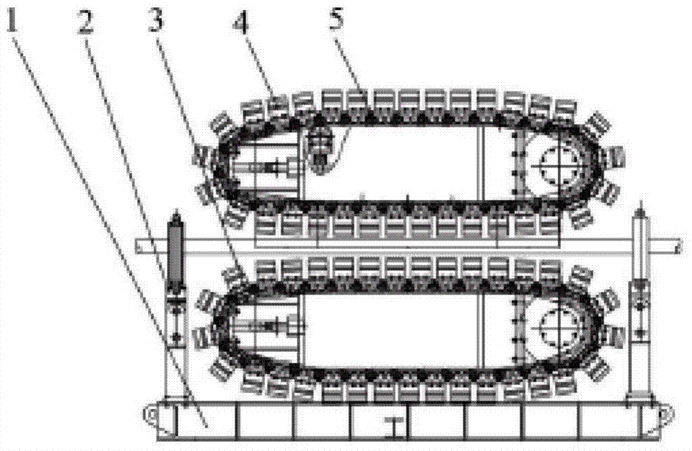
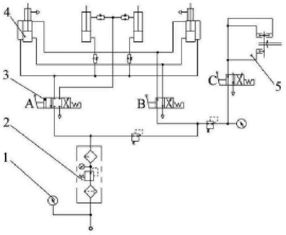
[0026] Refer to attached figure 1 , 2 Make the wire rope clamping device of the present invention.

[0027] The main technical parameters of the wire rope clamping device are shown in Table 1.

[0028] Table 1. Main technical parameters of wire rope clamping device

[0029] Maximum tension (kN)

98

Maximum speed (m / min)

30

Applicable wire rope diameter (mm)

40~76

Working air pressure (kg / cm 2 )

7~9.9

Brake rated torque (Nm)

8870

Track positive pressure (kN)

179

Working condition friction coefficient ζ

0.55

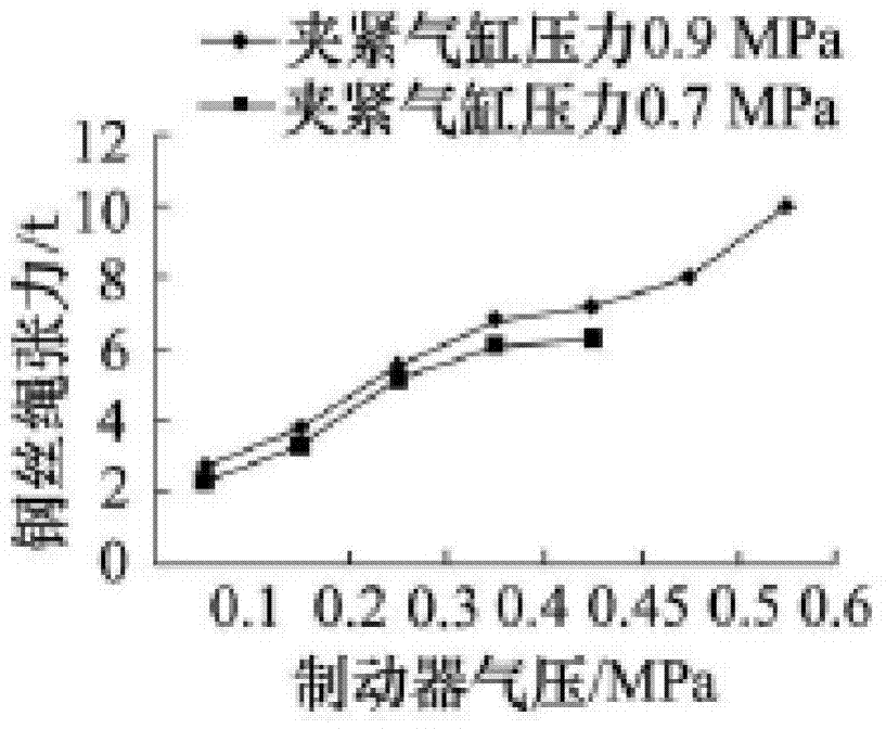
[0030] The steel wire rope clamping device can generate a constant damping force on the steel wire rope, and the steel wire rope will not produce rope disorder. The tension of the wire rope can be changed by adjusting the intake pressure of the brake. The tension of the wire rope is measured by the GGD-331 peak force gauge, and the graph of the tension of the wire rope and the adjustm...


PUM


Abstract

The invention discloses a steel wire rope clamping device based on air pressure transmission. The steel wire rope clamping device based on air pressure transmission comprises a steel wire rope clamping device, an air cylinder and a control cabinet. A cantilever double crawler and lower crawler ejecting and clamping structure is adopted in the steel wire rope clamping device and reasonable matching is achieved through an air pressure system, so that the clamping force of the crawlers on a steel wire rope is 25 times the tension value of the steel wire rope. Thus, self-adapting flexible control of the clamping force of an ejecting crawler and set tension is achieved. Under the condition that constant tension is exerted on the steel wire rope, the minimal deformation amount of the steel wire rope is automatically obtained and damage to the steel wire rope is avoided. In addition, constant damping force is exerted on the steel wire rope and rope disordering will not happen to the steel wire rope.

Description

technical field [0001] The invention relates to the field of wire rope pretension devices, in particular to a wire rope clamping device based on pneumatic transmission. Background technique [0002] Wire rope is one of the most important components in hoisting machinery and equipment, and is widely used in material handling, hoisting, winch traction, fishing trawl, and ship loading and unloading. The wire rope must be wound onto the wire rope drum accurately and accurately for the equipment to work safely and efficiently. The ideal form of wire rope winding on the drum is that it must start at one end of the drum, and every time the drum rotates a circle, the newly wound wire rope just falls between the strands of the lower layer of wire rope. This is especially problematic if the upper strands are at an angle to the lower strands. [0003] With the continuous increase of large-scale ship cranes in its projects, the problem of ensuring the safety of updated steel wire rope...

Claims


Application Information

Patent Timeline
Patent Type & Authority Applications(China)
IPC IPC(8): B66D1/28B66D1/54
Inventor 张浩
Owner WUXI UNIVERSAL STEEL ROPE
Why Eureka
Try Eureka