
A wheeled motor vehicle

An obstacle-breaking vehicle and maneuvering technology, applied in hoisting devices, hoisting devices, etc., can solve problems such as poor self-maneuvering ability, lack of slewing mechanism, and unsuitability for disaster rescue, so as to improve operating efficiency and avoid time delays Effect

Active Publication Date: 2015-09-30
ARCHITECTURAL ENG INST GENERAL LOGISTICS DEPT P L A
View PDF6 Cites 0 Cited by
  • Summary
  • Abstract
  • Description
  • Claims
  • Application Information

AI Technical Summary

Problems solved by technology

Several recent earthquake relief efforts have fully revealed several problems existing in existing construction machinery: first, poor self-maneuverability, mainly relying on flatbed transport vehicles for transportation, which is very likely to cause traffic jams and affect rescue time; second, single function, complete different tasks Obstacle clearance operations require a variety of construction machinery with different functions to cooperate in turn. Efficient rescue operations cannot be carried out at rescue sites with limited space, which affects rescue efficiency.
ZL99228129.6 describes a wheeled tractor with bulldozing and loading functions, but it cannot solve the problems of obstacle breaking, cutting, and removal of obstacles at the rescue site, and the tractor has poor maneuverability and is not suitable for disaster rescue use
ZL200310100745.7 describes a machine with excavation and loading functions, but does not have functions such as shoveling and crushing. Although the front end has a telescopic arm, it does not have a slewing mechanism. When lifting obstacles, it needs to be equipped with a whole vehicle to move, and the stability is very high. Poor, in addition, the machine needs to be transported on a flatbed when it is maneuvered over a long distance

Method used


Image

  • A wheeled motor vehicle
  • A wheeled motor vehicle
  • A wheeled motor vehicle

Examples


Embodiment Construction

[0032] The present invention will be further described in detail below in conjunction with specific embodiments of the drawings, which are explanations of the present invention rather than limitations.

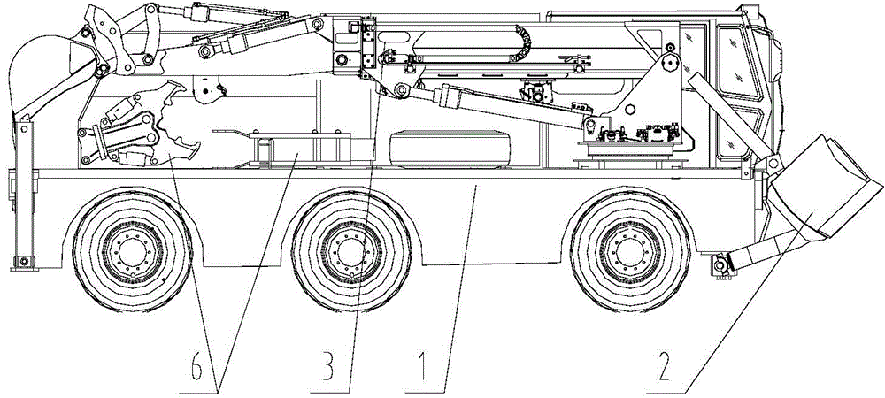
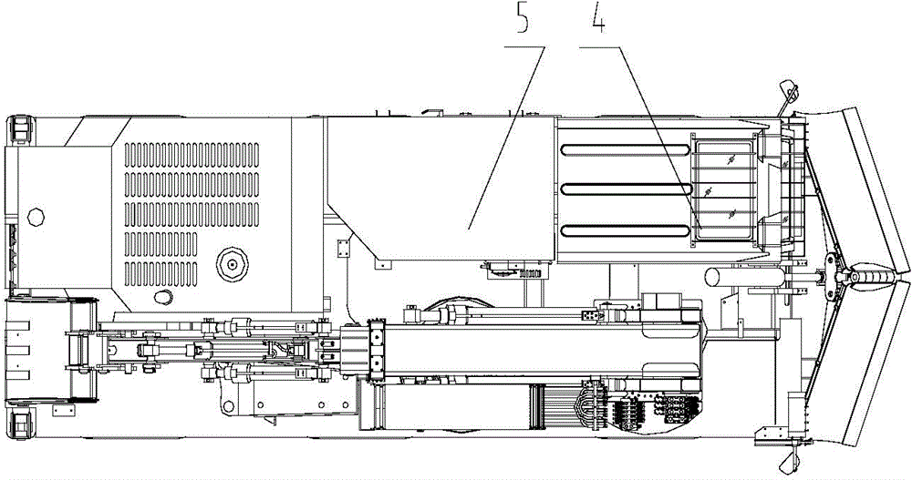
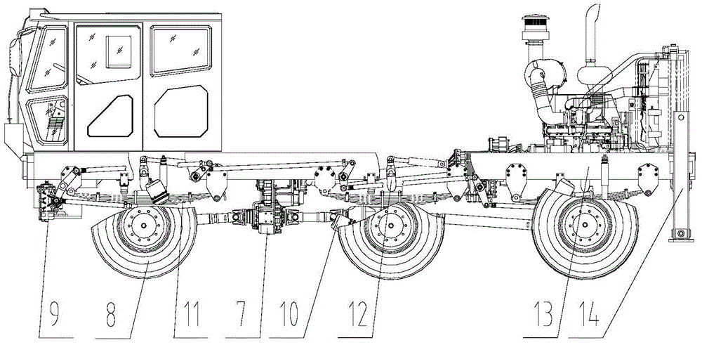
[0033] Such as figure 1 , 2 As shown, the wheeled motorized obstacle breaking vehicle includes a cab 4 and a motorized chassis 1, on which a telescopic boom arm compound operating mechanism 3 and a push-shoveling device 2 are arranged. The telescopic boom arm compound operating mechanism 3 is located above the side of the motorized driving chassis 1, and various operating attachments 6 are fixed between the telescopic boom arm and arm compound operating mechanism 3 and the motorized driving chassis 1. The rear is provided with a portable machine tool cabin 5, and the manual tools in the portable tool cabin 5 can also be used in the narrow space where the machine cannot be deployed, which greatly expands the use function of the machine, saves time for natural disaster rescue, ...


PUM


Abstract

The invention discloses a wheel type mechanic operating barrier removing vehicle and belongs to the technical field of engineering machinery. The wheel type mechanic operating barrier removing vehicle comprises a cab and a mechanic operating traveling chassis. A telescopic movable arm bucket rod combined type operation mechanism and a push shovel device are arranged on the mechanic operating traveling chassis, a wide-view frame is adopted by the cab, bullet-proof glass and protection armor are installed, and a portable tool cabin is further arranged behind the cab. The wheel type mechanic operating barrier removing vehicle has the automatic mechanic operating capacity so that the problems of time delay, traffic jam and the like when a flatbed trailer is used for conveying can be solved. The wheel type mechanic operating barrier removing vehicle has a plurality of barrier removing functions of breakage, shearing, lifting, digging, push shoveling and the like, can achieve various road clearing tasks and rescuing tasks in a rescuing site, the operation rate is high, and the wheel type mechanic operating barrier removing vehicle is suitable for various natural hazard rescues such as earthquake relief work and also suitable for other occasions with other engineering operation tasks.

Description

technical field [0001] The invention belongs to the field of construction machinery and relates to an obstacle breaking vehicle, in particular to a wheeled motorized obstacle breaking vehicle. Background technique [0002] In natural disaster rescue, the cleaning of landslides and landslides, the dredging of roads, the crushing and cutting of reinforced concrete, and the cleaning of obstacles at the rescue site all rely on various construction machinery with functions of pushing, digging, crushing, and lifting. Several recent earthquake relief efforts have fully revealed several problems existing in existing construction machinery: first, poor self-maneuverability, mainly relying on flatbed transport vehicles for transportation, which is very likely to cause traffic jams and affect rescue time; second, single function, complete different tasks Obstacle removal operations require a variety of construction machinery with different functions to cooperate in turn. Efficient resc...

Claims


Application Information

Patent Timeline
Patent Type & Authority Patents(China)
IPC IPC(8): B66F19/00
Inventor 辛涛侯忠明高勇王胜军赵晓文姚凯田新民
Owner ARCHITECTURAL ENG INST GENERAL LOGISTICS DEPT P L A
Learn More