
Rotary type automatic discharge electroplating rolling barrel

A technology for automatic unloading and electroplating barrels, applied in the electrolysis process, electrolytic components, etc., can solve the problems affecting the smooth automatic continuous operation of barrel plating production lines, increase labor costs for barrel covers, and increase maintenance costs for plating solutions. Electrochemical efficiency, simple structure, effect of reducing plating time

Inactive Publication Date: 2014-01-08
中山市瀚成电镀设备有限公司
View PDF8 Cites 21 Cited by
  • Summary
  • Abstract
  • Description
  • Claims
  • Application Information

AI Technical Summary

Problems solved by technology

[0007] Although the electroplating barrel has been improved in various aspects, the barrel cover has not been removed. The barrel cover increases labor costs and affects the automatic and continuous operation of the barrel plating production line. The barrel is responsible for the movement of products from various processes in barrel plating production. At the same time, the drum also brings some pollution to each plating solution, which increases the additional maintenance cost of the plating solution
The existing automatic barrel plating production line also designs and manufactures a mechanical device for automatically opening and closing the barrel lid of the barrel, but its structure is complex and takes a long time to execute, and it is limited to the beginning and end of the automatic production line.

Method used


Image

  • Rotary type automatic discharge electroplating rolling barrel
  • Rotary type automatic discharge electroplating rolling barrel
  • Rotary type automatic discharge electroplating rolling barrel

Examples


Embodiment Construction

[0024] Below, in conjunction with accompanying drawing and specific embodiment, the present invention is described further:

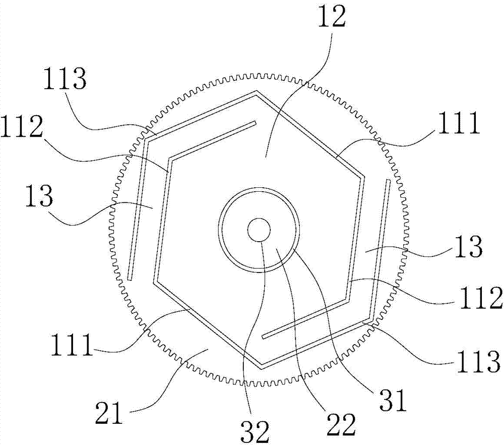
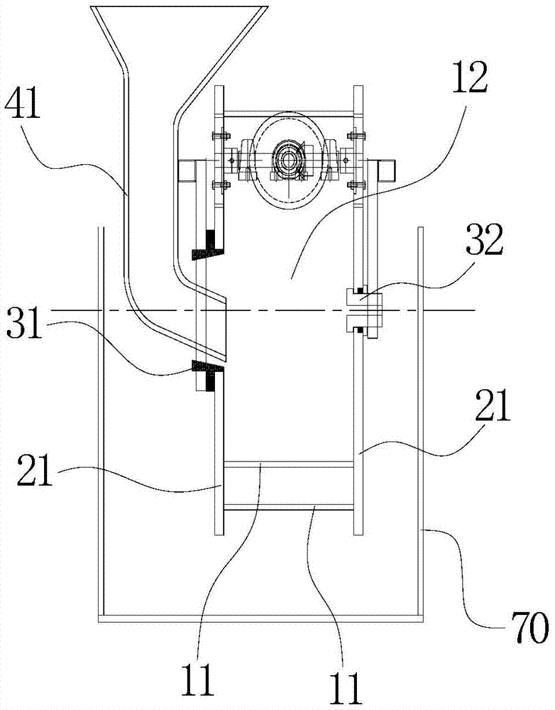
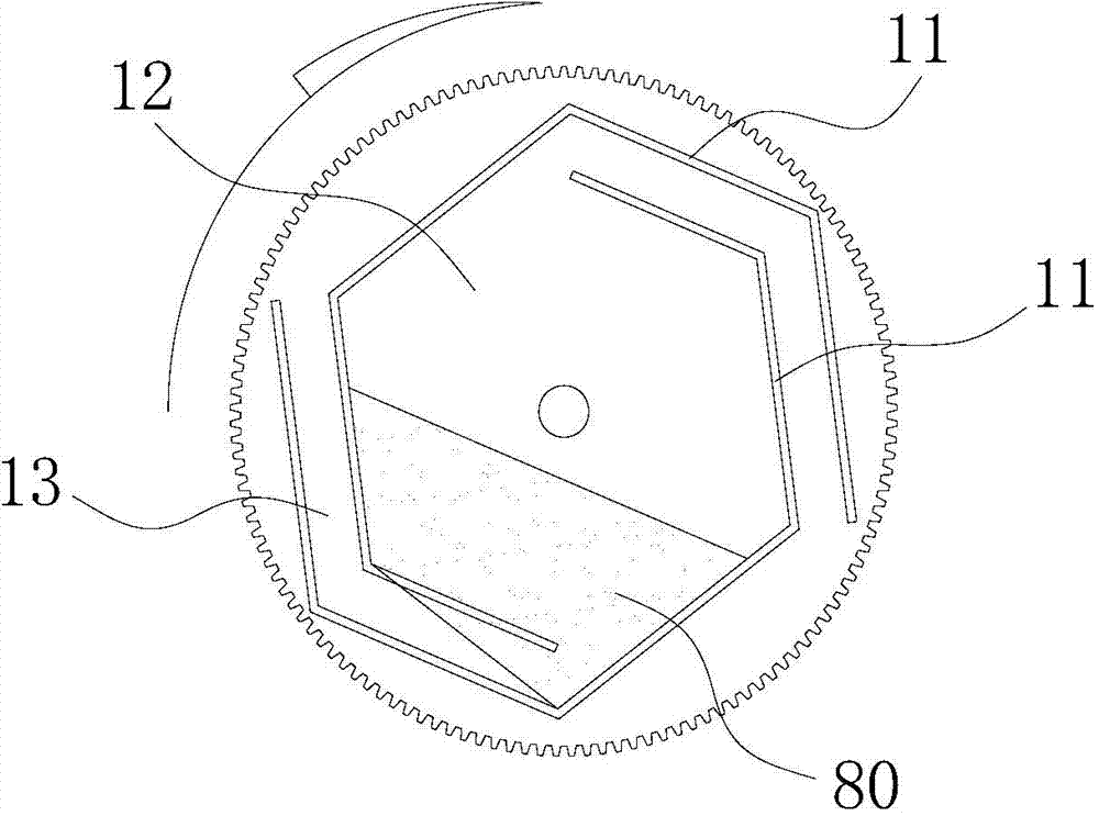
[0025] see figure 1 and figure 2 , the present invention discloses a rotary automatic unloading electroplating barrel, which includes a barrel body, a barrel cover and a rotating shaft. The barrel body is composed of two baffles 11 with a C-shaped cross-section and an opening. Each baffle 11 each includes a bottom wall 111 opposite to its opening, an inner side wall 112 and an outer side wall 113 respectively connected to both sides of the bottom wall 111. The directions facing each other are misaligned, and the electroplating cavity 12 is formed between the bottom wall 111 and the inner side wall 112 of the two baffle plates 11, and the discharge material is formed between the inner side wall 112 of one baffle plate 11 and the outer side wall 113 of the other baffle plate 11. Groove 13, discharge groove 13 communicates with electroplating cavity 12....


PUM


Abstract

The invention discloses a rotary type automatic discharge electroplating rolling barrel which comprises a barrel body, a barrel cover and a rotating shaft, wherein the barrel body comprises two baffle plates with C-shaped sections and openings; each baffle plate comprises a bottom wall, an inner side wall and an outer side wall; the bottom wall is opposite to the opening of the baffle plate; the inner side wall and the outer side wall are respectively connected to both sides of the bottom wall; the two baffle plates are mutually jogged in such a way that the openings are just opposite, the two baffle plates are mutually staggered in a direction perpendicular to a direction which is just opposite to the openings of the two baffle plates; electroplating cavities are formed between the bottom walls and inner side walls of the two baffle plates; a discharge chute is formed between the inner side wall of one baffle plate and the outer side wall of the other baffle plate, and the discharge chute is communicated with the electroplating cavity. According to the invention, the barrel body is designed into a structure that the two baffle plates with C-shaped sections are mutually jogged, so that the electroplating and the automatic discharge function can be realized, and the electroplating production continuity can be ensured. The rotary type automatic discharge electroplating rolling barrel disclosed by the invention is simple in structure and convenient to clean and farthest reduces the cross contamination of chemical raw materials among procedures.

Description

[0001] technical field [0002] The invention relates to a device in the barrel plating process, in particular to a rotary automatic unloading electroplating barrel. Background technique [0003] The electroplating barrel is an indispensable core equipment component in the barrel plating process. The existing drums in the market are usually cylindrical or multi-faceted cylindrical airtight components with holes processed in multi-faceted arrays. This structure has a drum cover, and the drum cover must be opened or closed every time the material is loaded and discharged during use. In the commonly used electroplating process, from the pre-treatment stage → electroplating of several metal types → post-treatment such as sealing or passivation after plating, due to the different formulations of the chemical liquid in each treatment tank of the electroplating process, the requirements for the content of the ingredients are also very strict , when a substance that has a destructi...

Claims


Application Information

Patent Timeline
IPC IPC(8): C25D17/20
Inventor 梅苏鸿
Owner 中山市瀚成电镀设备有限公司
Learn More