A New Multi-channel Distributed Disturbance Sensing System

A sensing system and multi-channel technology, which is applied in the field of new multi-channel distributed disturbance sensing system, can solve the problems of regional defense failure, complex system structure, slow response of OTDR, etc.

Inactive Publication Date: 2016-02-03
UNIV OF ELECTRONICS SCI & TECH OF CHINA
View PDF5 Cites 1 Cited by
  • Summary
  • Abstract
  • Description
  • Claims
  • Application Information

AI Technical Summary

Problems solved by technology

At present, there is a multi-channel expansion method for the distributed temperature sensing system. The patent (CN201110264324) proposes that the upper computer is connected in parallel with multiple photoelectric modules through the bus interface, and multiple optical switches can be connected as needed to expand the system channel without considering system detection. time, but the structure of the system is complex, and there is no diagnosis, location and processing of faulty links in practical applications, and the inventive method is mainly aimed at distributed temperature sensing systems
[0004] In addition, once a broken cable fault occurs in the distributed disturbance sensing system during the monitoring process, it will lead to the failure of the defense in a large area behind the broken cable.
At present, cable breakage faults are usually determined by a special OTDR, but the OTDR responds slowly, and the disturbance monitoring needs to be suspended during the cable breakage diagnosis. How to realize fault diagnosis and location while disturbing the sensing, and realize the online uninterrupted monitoring of the system is the key An important issue that urgently needs to be resolved

Method used


Image

  • A New Multi-channel Distributed Disturbance Sensing System

Examples


Embodiment Construction

[0016] Below with reference to accompanying drawing, the present invention will be further described:

[0017] The invention is a multi-channel distributed disturbance sensing system with the functions of multi-channel control, link fault diagnosis and backup link self-starting.

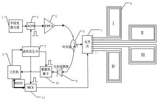
[0018] As a first embodiment, the system is composed as follows figure 1 As shown, it includes: narrow linewidth laser 1, host computer 2, waveform generation card 3, acousto-optic modulator (AOM) 4, erbium-doped fiber amplifier (EDFA) 5, circulator 6, 1×8 optical switch 7, detection Optical cable 8, photodetector 9, data acquisition card 10, microcontroller (MCU) 11 and other main parts.

[0019]The working process of the system is as follows: the narrow linewidth laser 1 emits strong coherent continuous light, enters the acousto-optic modulator (AOM) 4 to modulate the pulsed light, and the pulsed light amplified by the erbium-doped fiber amplifier (EDFA) 5 passes through the circulator 6 Port 1-2...


PUM


Abstract

The invention proposes a novel multi-channel distributed disturbance sensing system. According to the characteristics of the distributed disturbance sensing system based on optical time domain reflectometry, without increasing the cost of the sensing system, the multi-channel is expanded through the optical switch to realize the simultaneous monitoring of multiple areas and multiple lines. The link backup function on each line; use the microcontroller to control the optical switch to realize multi-channel cyclic switching, and at the same time communicate with the serial port of the host computer to realize multi-channel identification; use the system's own optical time domain signal to realize real-time self-diagnosis and monitoring of broken cable faults Positioning and other functions, and the use of microcontrollers to automatically enable the backup link after a cable breakage occurs, to achieve real multi-channel, multi-line and multi-zone online uninterrupted with link fault diagnosis and link backup functions Monitoring and protection.

Description

technical field [0001] The invention belongs to the technical field of distributed optical fiber sensing, and in particular relates to a novel multi-channel distributed disturbance sensing system with multi-channel control, link fault diagnosis and backup link self-activation. Background technique [0002] The distributed disturbance sensing system based on optical time domain reflection technology usually consists of three parts: monitoring optical cable, demodulation equipment and central processing unit. , barbed wire, fences, etc., convert various disturbance signals such as vibration and strain on the transmission cable path into optical information, perform real-time reception, collection and intelligent analysis, processing and identification, and realize early warning and monitoring of threat behaviors invading the perimeter of the fortified area And 24 hours a day uninterrupted real-time monitoring. [0003] This type of system is usually expensive, mainly dependin...

Claims


Application Information

Patent Timeline
Patent Type & Authority Patents(China)
IPC IPC(8): G01D5/353
Inventor 吴慧娟许基伟肖舜坤饶云江
Owner UNIV OF ELECTRONICS SCI & TECH OF CHINA
Why Eureka
Try Eureka