Micro-field-of-view bilateral dynamic in-situ micro-torsion material mechanical property tester

A technology of torsion materials and microscopic field of view, applied in scientific instruments, analytical materials, instruments, etc., can solve the problems of little or no consideration of the accuracy of the position of the specimen, restrictions on the in-depth and development of research, and lack of test content. Achieve the effect of stable test process, compact structure and small torsion angle

Active Publication Date: 2014-01-08
JILIN UNIV +1
View PDF5 Cites 20 Cited by
  • Summary
  • Abstract
  • Description
  • Claims
  • Application Information

AI Technical Summary

Problems solved by technology

In this way, the area observed by the imaging instrument will also be twisted. Therefore, during the test process, the observed area will continue to disappear from the field of view, which brings a lot of inconvenience to the online observation of the experiment; secondly, due to the in-situ test instrument Due to the limitation of the overall volume, the fixture configured by the instrument cannot be too large, which affects the clamping accuracy of the specimen. Most of the fixtures on the in-situ torsion test instrument developed at present only consider the clamping of the specimen tightness, but little or no consideration is given to the accuracy of the position of the specimen; moreover, the torsion test for macroscopic materials with a characteristic size above the millimeter level is mainly an ex-situ test with the help of a commercial torsion testing machine , does not involve in-situ testing in the environment where imaging instruments such as scanning electron microscopes are used
And it shows that the equipment is relatively expensive and the test content is lacklustre, which greatly restricts the in-depth and development of research.

Method used


Image

  • Micro-field-of-view bilateral dynamic in-situ micro-torsion material mechanical property tester
  • Micro-field-of-view bilateral dynamic in-situ micro-torsion material mechanical property tester
  • Micro-field-of-view bilateral dynamic in-situ micro-torsion material mechanical property tester

Examples


Embodiment Construction

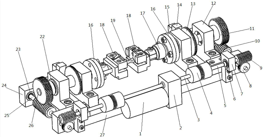
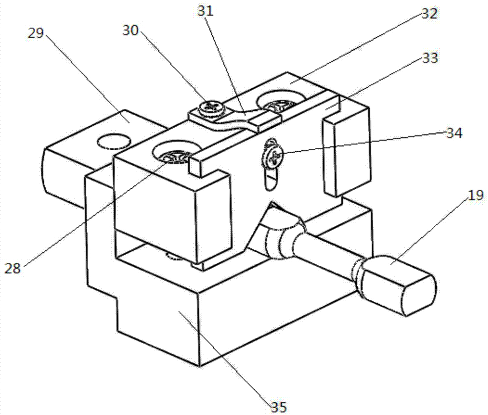
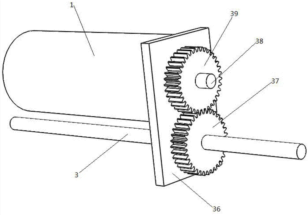
[0017] The invention includes a base, a DC servo motor, a gearbox, an elastic coupling, a main shaft, and a fixture. The axes of the two main shafts are on the same straight line, and the two main shafts are equipped with fixtures, torque sensors, flanges, reading head connecting frames, circular grating reading heads, and circular grating scales in sequence from the front section to the rear. Shaft connections gain torque. A further technical solution is that the transmission device is a worm gear pair consisting of a high-speed worm gear and a low-speed worm gear, the high-speed worm is connected with an elastic coupling, and the low-speed worm gear is installed at the rear end of the main shaft. The fixture is composed of an upper platen and a lower platen. The upper platen and the lower platen are connected by clamping bolts. There is a positioning groove at the front end of the upper platen. There is a positioning piece in the positioning groove. The lower end of the posi...


PUM


Abstract

Disclosed is a micro-field-of-view bilateral dynamic in-situ micro-torsion material mechanical property tester. The tester comprises a base, a direct-current servo motor, a transmission, elastic couplings, two spindles and clamps. The tester is characterized in that the transmission is provided with a left bilaterally-through output shaft and a right bilaterally-through output shaft, the left spindle and the right spindle are arranged on the base oppositely, axes of the two spindles are on a same straight line, each spindle is provided with the corresponding lamp, a torque sensor, a flange, a reading head connector, a circular grating reading head and a circular grating sequentially from front to back, and the rear end of each spindle is connected with the corresponding output shaft trough a transmission gear to acquire torque. The tester is compact in structure, small in size, controllable in angular strain rate and convenient to operate, has good use compatibility with imaging apparatuses and can perform whole-process all-round in-situ monitoring on micro deformation, damage and breakage processes on materials, and a novel testing instrument and method is provided for revealing mechanical properties and damage mechanisms of the materials in micro-nano scale.

Description

technical field [0001] The invention relates to a material test and detection instrument, in particular to a double-sided dynamic in-situ micro-torsion material mechanical performance tester under a microscopic field of view. Background technique [0002] Torsion test is one of the basic test methods of material mechanical performance test. The strength and plasticity of brittle materials and plastic materials can be determined by torsion test to evaluate the performance of materials. The test results of the traditional torsion testing machine are all based on the change amount after the load is applied, and cannot monitor the dynamic process of material changes, damage and even destruction in real time during the load implementation. In order to explore and reveal the macro-micro cross-scale dynamic deformation behavior of solid materials under torsion and other loads, a few institutions at home and abroad are working on the development and development of combined electron...

Claims


Application Information

Patent Timeline
Patent Type & Authority Applications(China)
IPC IPC(8): G01N3/26G01N3/04
Inventor 张志辉王书鹏任露泉赵宏伟梁云虹朱冰李凌余轩
Owner JILIN UNIV
Why Eureka
Try Eureka