Networking method for emergency communication network for mining area and communication system for mining area

A technology of communication system and communication network, which is applied in the field of networking method and communication system of emergency communication network used in mining areas, which can solve the problems of negative impact on rescue work, low transmission bandwidth, and few hops in communication paths, etc., to achieve improved uninterrupted The effect of transmission ability, solving mutual interference, and reducing communication power consumption

Active Publication Date: 2014-01-08
BEIJING GENERAL RES INST OF MINING & METALLURGY
View PDF6 Cites 8 Cited by
  • Summary
  • Abstract
  • Description
  • Claims
  • Application Information

AI Technical Summary

Problems solved by technology

This kind of emergency communication network based on the wired communication system is not only difficult to deploy, but once the cable breaks or the power supply is interrupted due to an accident in the mining area, the entire emergency communication network will be unusable, which will have a serious negative impact on the rescue work.
[0005] (2) Emergency communication networks based on PHS, walkie-talkie or through-the-earth communication technology: These emergency communication networks mainly rely on PHS, walkie-talkie or through-the-earth communication technology for voice transmission, but their transmission bandwidth is very low and cannot Complete comprehensive emergency rescue communication
[0006] (3) Emergency communication network based on Wi-Fi technology: the existing emergency communication network based on Wi-Fi technology adopts single radio frequency transmission technology and half-duplex radio frequency working mode, so this emergency communication network The radio frequency unit needs to switch between the signal coverage mode and the routing and forwarding mode in stages; this makes the limited transmission bandwidth be dispersed and applied to different transmission stages, thus greatly reducing the overall transmission rate and reliability of the emergency communication network , so the existing Wi-Fi technology-based emergency communication network is not suitable for emergency rescue communication, which is a high-reliability communication service with multiple concurrent signals and real-time transmission of large amounts of data.
[0007] In addition, the existing wireless communication system mainly adopts the networking method of Mesh (wireless mesh network) or the networking method based on AODV (Ad hoc on-demand distance vector routing, which is a source-driven routing protocol) routing protocol for self-organization. network, but both of these two networking methods have some disadvantages, so they are not suitable for use in emergency communication networks in mining areas
Specifically, if the network is based on mesh networking, the cost of the wireless communication system after the completion of the network is very high, and the power consumption is high. Not only can it not be popularized in a large area, but also the communication time of the emergency communication network is greatly shortened. , which seriously affects the rescue progress, so it is not suitable for emergency communication network used in mining areas with long communication time, high reliability and real-time requirements
If the networking is based on the AODV routing protocol, the communication path after the networking is usually less hops, the distance between the two nodes of each hop is relatively large, and the RSSI (Received Signal Strength Indication, received signal strength indication) is low, and the transmission rate will slow down, which will lead to a decrease in the data throughput of the node and an increase in communication delay, so it is not suitable for applications with large amounts of data and concurrency High and real-time emergency communication network for mining area

Method used


Image

  • Networking method for emergency communication network for mining area and communication system for mining area
  • Networking method for emergency communication network for mining area and communication system for mining area
  • Networking method for emergency communication network for mining area and communication system for mining area

Examples


Embodiment 1

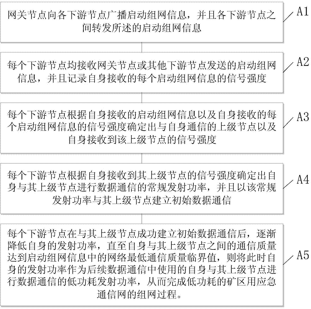
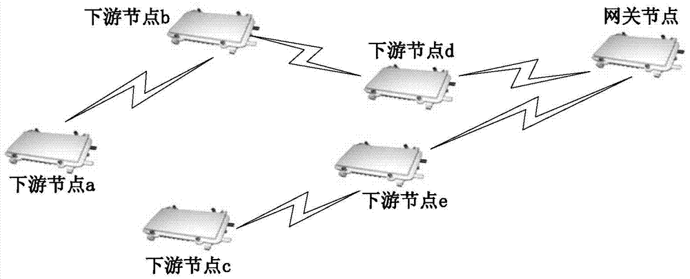
[0048] Embodiment 1: as figure 2 As shown, it is a communication system applying the networking method provided by the present invention; the gateway node broadcasts the starting networking information to each downstream node in the network domain; the specific processing of each downstream node in this process is as follows:

[0049] (1) The starting networking information received by downstream node d for the first time can be sent by the gateway node. This time, downstream node d updates and forwards the starting networking information; downstream node d can then receive downstream node e, downstream node The network start information sent by c and the downstream node b does not update or forward the start network information to the downstream node d.

[0050] (2) The starting networking information received by downstream node e for the first time can also be sent by the gateway node. This time, downstream node e updates and forwards the starting networking information; do...


PUM


Abstract

The invention discloses a networking method for an emergency communication network for a mining area and a communication system for the mining area. Due to the facts that each downstream node carries out communication by selecting an upper-level node which is the shortest in path and the strongest in signal receiving, and the emission power of each downstream node is gradually reduced to be at passable lowest level, the communication network with low power consumption can be established flexibly and rapidly; due to the fact that the multi-radio-frequency communication mode is adopted, the problem of mutual interference between terminal access and a network cascade channel is effectively solved, the network connection rate is increased and the continuous transmission capacity of comprehensive data services is improved. Therefore, a high-quality scheme is provided for establishment, maintenance and use of the low-power-consumption emergency communication network for the mining area, powerful communication support is provided for emergency rescue of accidents in the mining area.

Description

technical field [0001] The invention relates to the technical field of mining area communication, in particular to a networking method and communication system for an emergency communication network used in a mining area. Background technique [0002] In recent years, accidents in various mining areas have occurred frequently, which not only seriously affects the economic benefits of the mining area, but also poses a serious threat to the life safety of the mining area workers. In accident rescue in mining areas, emergency communication network is an important means to implement effective rescue, and can provide effective guarantee for rescue dispatching, personnel contact and emergency command. Therefore, the traffic status of emergency communication network in mining area is an important factor affecting the rescue results. [0003] At present, the existing emergency communication networks for mining areas mainly include: emergency communication networks based on wired com...

Claims


Application Information

Patent Timeline
Patent Type & Authority Applications(China)
IPC IPC(8): H04W40/12H04W52/02
CPCY02D30/70
Inventor 金枫战凯张达刘旭吕潇陆得盛余斌杨小聪刘建东
Owner BEIJING GENERAL RES INST OF MINING & METALLURGY
Why Eureka
Try Eureka