Fast starting circuit for crystal oscillators

a crystal oscillator and fast technology, applied in the field of crystal oscillators, can solve the problems of high power consumption of crystal oscillators, inability to obtain radio-frequency clock signals, and inability to achieve significant overall operating tim

Active Publication Date: 2009-06-30
APPLE INC
View PDF10 Cites 3 Cited by
  • Summary
  • Abstract
  • Description
  • Claims
  • Application Information

AI Technical Summary

Benefits of technology

[0019]Immediately after the supply voltage for the crystal oscillator has been switched on, the crystal oscillator will not yet have been stabilized, but it emits an output signal with voltage variations corresponding to the self-noise of the oscillating crystal, with noise effects and initial oscillations contained in it. These voltage variations are detected in the first step of the feedback method according to the invention. A detected voltage variation is used to produce an excitation pulse, which is emitted to the electromechanical oscillator. The time which passes from detection of a voltage variation to the feeding of the excitation pulse which is produced from it is in general negligible in comparison to the oscillation duration of the electromechanical oscillator. The excitation pulses are thus fed to the electromechanical oscillator instantaneously, on the timescale of the oscillator oscillation, after the detection of a voltage variation or of an oscillator oscillation in the output signal from the electromechanical oscillator. The voltage variation which is detected in the first step of the feedback method is thus amplified with the correct phase. As soon as voltage variations can be detected in the output signal from the electromechanical oscillator, these or the mechanical oscillations of the electromechanical oscillator on which they are based are deliberately amplified by using the instantaneously generated excitation pulses that are fed in to drive additional charges into the electromechanical oscillator. The oscillation amplitude of the voltage variation or of the oscillator oscillation of the electromechanical oscillator is increased in this way.
[0020]The method according to the invention deliberately amplifies noise effects and initial oscillations of the electromechanical oscillator, and the oscillation amplitude of the electromechanical oscillator increases considerably faster than in the case of known methods for switching on an electromechanical oscillator. In consequence, the full oscillation amplitude of the electromechanical oscillator, that is to say the steady state, is reached considerably more quickly, and the oscillation starting process is thus significantly shortened. The useable radio-frequency clock or oscillator signal is thus available considerably more quickly after the electromechanical oscillator has been switched on, and the time in which the electromechanical oscillator is not emitting any useable radio-frequency clock signal even though it is consuming power is reduced. The electromechanical oscillator is thus operated in a considerably more energy-saving manner, since the overall operating time of the electromechanical oscillator is reduced. The method according to the invention lengthens the possible operating time of communications terminals which are independent of the mains system.
[0025]However, the feeding of an excitation pulse to the electromechanical oscillator excites not just the intended oscillation frequency but also harmonics and other undesirable oscillations. The insertion of pauses or gaps between successive excitation pulses allows the undesirable harmonics to decay, and thus contributes to the electromechanical oscillator oscillating only at the intended oscillator frequency. Carrying out the feedback method according to the invention repeatedly results in the oscillation amplitude of the electromechanical oscillator being additionally amplified, and accordingly makes a contribution to further shortening the oscillation starting time.
[0029]The apparatus according to the invention for assisting the oscillation starting process of an electromechanical oscillator and for carrying out the method according to the invention comprises a detection unit for detection of oscillator oscillations which occur in the output signal from the electromechanical oscillator and of voltage variations which are present in the self-noise of the electromechanical oscillator and are caused, for example, by noise effects and initial oscillations, as well as a pulse generator for production of an excitation pulse on the basis of a detected oscillator oscillation, which excitation pulse is fed to the electromechanical oscillator. In general, the signal delay times through the detection unit and the pulse generator of the apparatus according to the invention are negligible in comparison to the oscillation duration of the electromechanical oscillator, so that the excitation pulse which is produced on the basis of a detected oscillator oscillation is fed to the electromechanical oscillator instantaneously, on the timescale of the (slower) oscillator oscillation, and thus with the correct phase. This results in additional charges being driven into the crystal, and the oscillation amplitude of the electromechanical oscillator is increased.
[0031]In one particularly preferred refinement of the apparatus according to the invention, the detection unit comprises an inverter chain for amplification of oscillator oscillations which occur in the output signals from the electromechanical oscillator, and for production of the clock signal. In a further preferred refinement, at least one of the inverters in the inverter chain, but in particular all of the inverters in the inverter chain, is or are operated at the triple point, that is to say the output of the respective inverter is fed back through a high impedance to its input. The input and the output of the inverter thus assume the same voltage level in the rest state, with this being between the two logic voltage levels. The inverter is thus in a state in which it produces the highest gain and can quickly amplify voltage variations which occur. This analogue operation of an inverter, in particular of a CMOS inverter, results in a faster amplifier of simple design.
[0038]The oscillator circuit according to the invention comprises an oscillator unit with an electromechanical oscillator, as well as an apparatus according to the invention for assisting the oscillation starting process of an electromechanical oscillator. The addition of the apparatus according to the invention for assisting the oscillation starting process of an electromechanical oscillator to the known oscillator unit ensures that a stable-frequency clock or oscillator signal is produced even after an oscillation starting period of the electromechanical oscillator which is considerably shorter than that in the prior art.

Problems solved by technology

Crystal oscillators have a high power consumption, which is particularly disadvantageous in battery-powered terminals or terminals which are independent of the mains system, such as mobile telephones, since the comparatively high energy consumption shortens the operating time of such terminals which are independent of a mains system.
If the radio-frequency clock signal is likewise required only for a few milliseconds, then the oscillation starting process of the crystal oscillator is lengthened, during which process the radio-frequency clock signal, whose overall operating time is significant, is not yet available.

Method used


Image

  • Fast starting circuit for crystal oscillators
  • Fast starting circuit for crystal oscillators
  • Fast starting circuit for crystal oscillators

Examples


Embodiment Construction

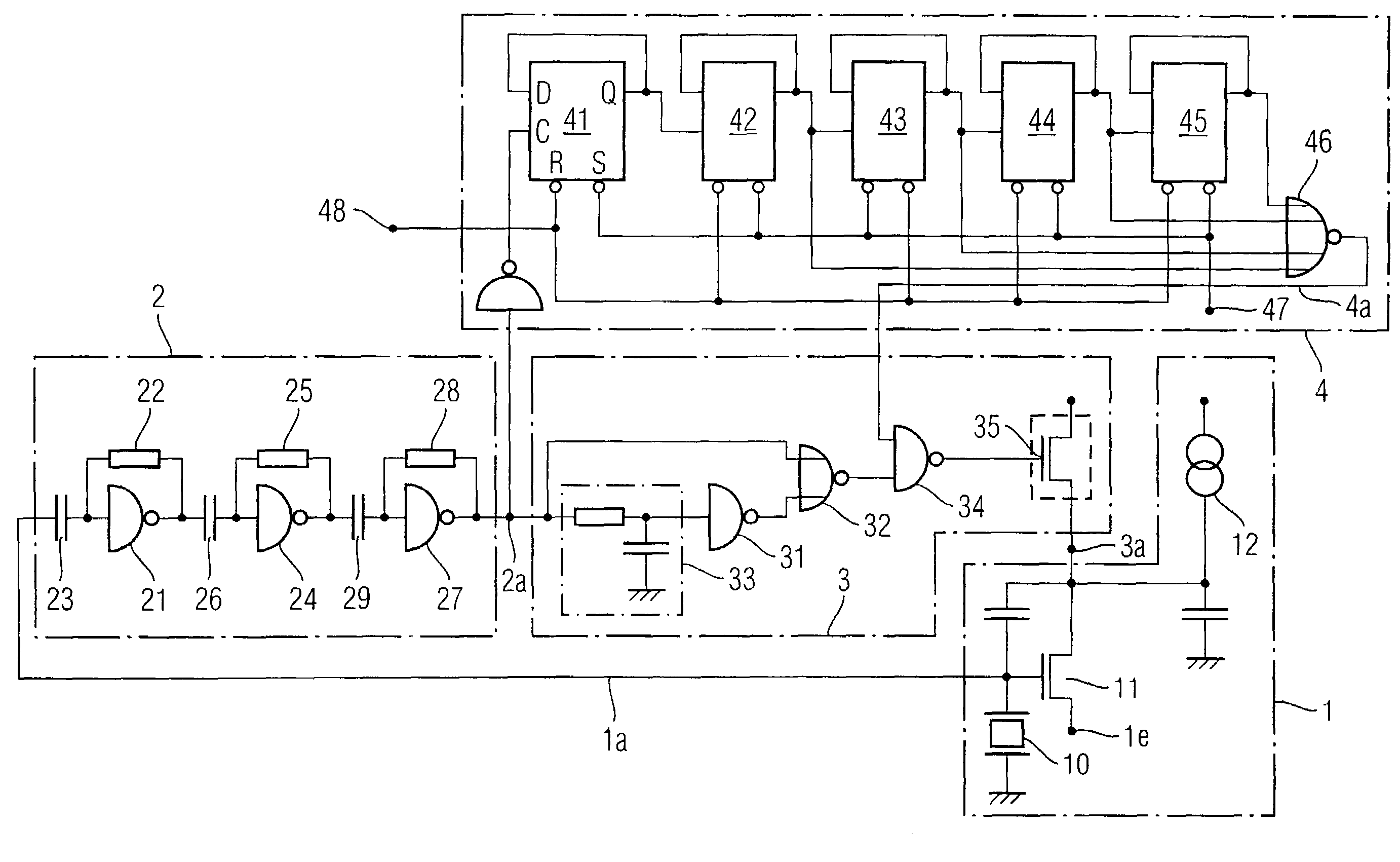
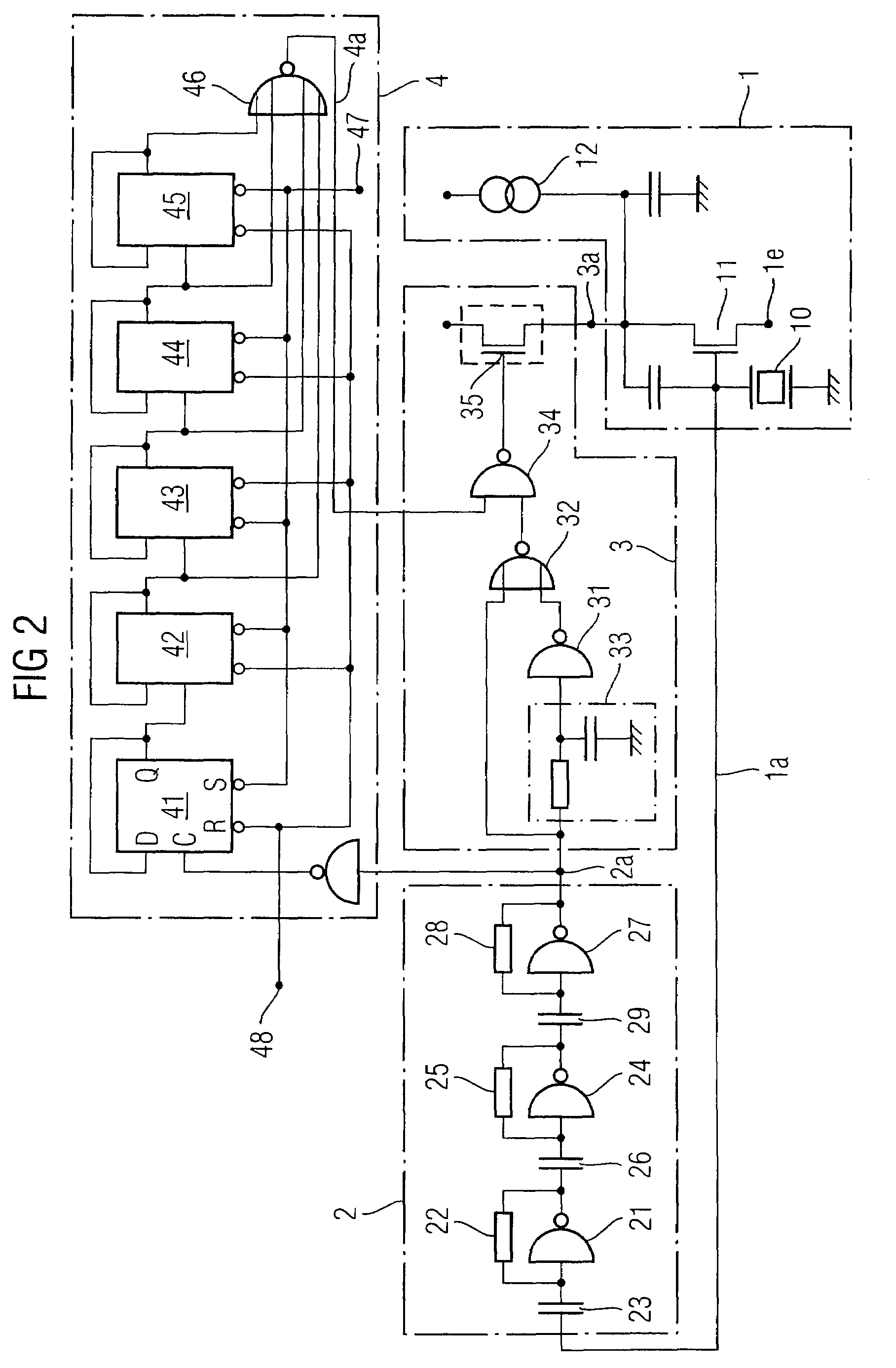
[0045]FIG. 2 shows the circuit diagram of one exemplary embodiment of the oscillator circuit according to the invention. The oscillator circuit comprises an oscillator unit 1 with a crystal oscillator or oscillating crystal 10. A controlled current source 12 supplies a switching transistor 11, whose gate is controlled by the oscillating crystal 10. The controlled current source 12 may be controlled, for example, in such a way that it emits a higher voltage during the oscillation starting process, in order to speed up the oscillation starting process. A stabilized-frequency clock signal is emitted at the connection 1e of the switching transistor. The output signal from the oscillating crystal 10 is supplied via the supply line 1a (XTAL) to a detection unit 2. A pulse generator 3 feeds excitation pulses 3b with the correct phase via the supply line 3a (LOAD PIN) to the oscillator unit 1.

[0046]Immediately after the supply voltage for the oscillator unit 1 is switched on, the oscillatin...


PUM


Abstract

A method for assisting the oscillating starting process of an electromechanical oscillator (10) has the following steps: detection of oscillator oscillations (1b, 1c) which occur in the output signal (1a) from the electromechanical oscillator (10); generation of an excitation pulse (3b) on the basis of a detected oscillator oscillation (1c); and feeding (3a) of the excitation pulse (3b) to the electromechanical oscillator (10).

Description

PRIORITY[0001]This application claims priority from German Patent Application No. DE 10 2005 001 684.7, which was filed on Jan. 13, 2005, and is incorporated herein by reference in its entirety.TECHNICAL FIELD[0002]The invention relates to a method and an apparatus for assisting the oscillation starting process of electromechanical oscillators, in particular crystal oscillators.BACKGROUND[0003]In order to interchange data between different communication terminals, an identical clock or oscillator signal is required for the transmission and reception of data in the subscriber appliances. When interchanging data via radio links, this is generally a radio-frequency clock or oscillator signal (for example at 2 GHz or more). This clock or oscillator signal must be produced in the various communication terminals independently of one another, for which reason the individual clock signals must be highly frequency stable, in order to maintain synchronicity between the subscriber appliances. ...

Claims


Application Information

Patent Timeline
Patent Type & Authority Patents(United States)
IPC IPC(8): H03L7/24H03B5/36
CPCH03B5/06H03B5/36H03L3/00
Inventor CHRIST, VOLKER
Owner APPLE INC
Why Eureka
Try Eureka