

Saddle-type vehicle
A straddle-type, vehicle technology, applied to vehicle parts, motorcycles, bicycles, etc., to achieve the effect of reducing weight and cost, reducing weight and cost, and improving assembly workability
- Summary
- Abstract
- Description
- Claims
- Application Information
AI Technical Summary
Problems solved by technology
Method used
Image

Examples
Embodiment Construction
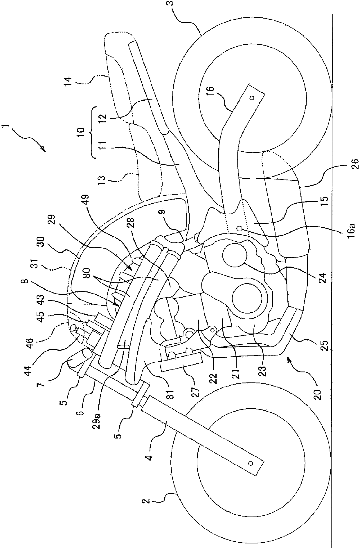
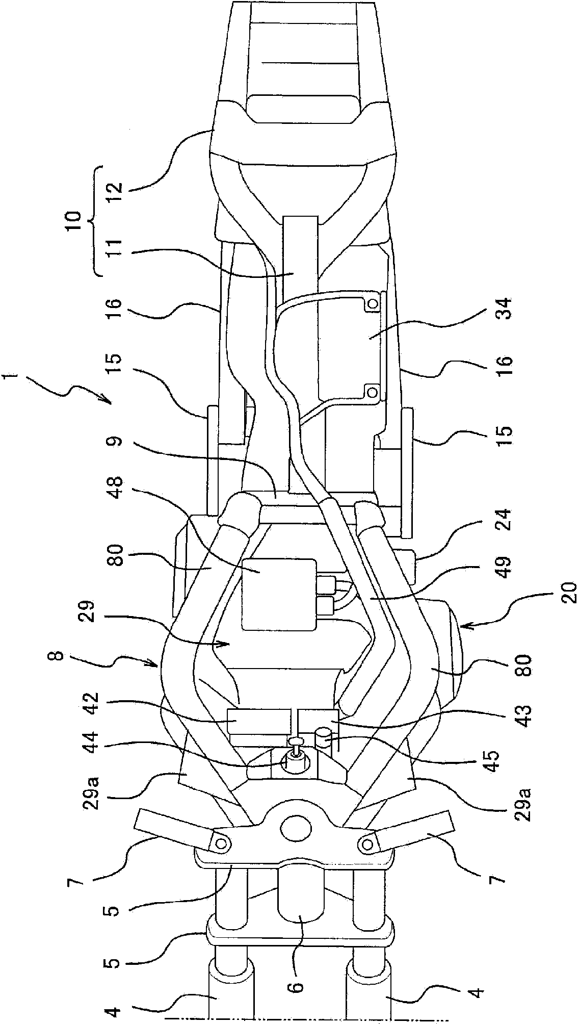
[0036] Hereinafter, a motorcycle 1 (a straddle-type vehicle) according to an embodiment of the present invention will be described with reference to the drawings. figure 1 It is a left side view showing a schematic structure of the motorcycle 1 with lamps, fairings, etc. removed, figure 2 It is a top view with the fuel tank and seats removed. In addition, the concept of direction used in the following description is based on the direction seen by a driver (user) riding a motorcycle.
[0037] The motorcycle 1 includes a front wheel 2 as a driven wheel, and a rear wheel 3 as a driving wheel. The front wheel 2 is rotatably supported by the lower ends of a pair of left and right front forks 4 extending approximately in the vertical direction, and the upper portion of the front forks 4 is supported by a steering shaft (not shown) via a pair of upper and lower brackets 5 . The steering shaft is inserted and rotatably supported in a head pipe 6 constituting a part of the body fram...
PUM
 Abstract
Description
Claims
Application Information