
Scroll compressor

A technology of scroll compressors and orbiting scrolls, applied in the direction of rotary piston machinery, rotary piston pumps, mechanical equipment, etc., can solve the problems of small reduction effect, difficulty in forming oil film, limitation, etc., to reduce bearing loss, Effect of reducing shear resistance

Active Publication Date: 2014-01-08
HITACHI JOHNSON CONTROLS AIR CONDITIONING INC
View PDF9 Cites 7 Cited by
  • Summary
  • Abstract
  • Description
  • Claims
  • Application Information

AI Technical Summary

Problems solved by technology

[0014] However, in the structure of the above-mentioned Patent Document 1, the number of components increases, so the structure becomes complicated, and the number of sliding parts also increases, and new problems arise, such as requiring high management accuracy of the bearing gap size.
In addition, during low-speed operation, due to the reduction of sliding speed, it is difficult to form an oil film, so there is also a problem that direct contact with the sliding bush is likely to occur.
[0015] In addition, the structure of the above-mentioned Patent Document 2 is effective in promoting the inflow of lubricating oil from the outside to the bearing gap to prevent oil film rupture and prevent direct contact between the shaft and the bearing. There is a notch in the place where the gap is large, so the reduction of the shear resistance of the fluid lubricating oil film cannot be expected, or the reduction effect is small
Therefore, once a fluid lubricating oil film is formed to form a state where there is no direct contact part, the loss reduction above this cannot be achieved or is limited.

Method used


Image

  • Scroll compressor
  • Scroll compressor
  • Scroll compressor

Examples


Embodiment 1

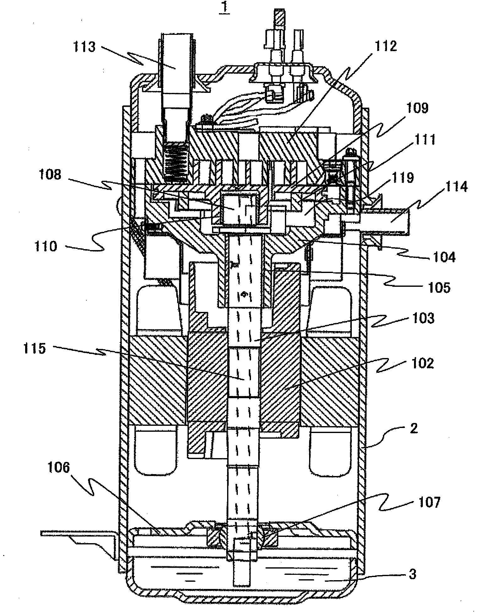
[0037] figure 1 It is a longitudinal sectional view showing Embodiment 1 of the scroll compressor of the present invention.

[0038] figure 1 The illustrated scroll compressor 1 is a hermetic scroll compressor used for refrigeration and air conditioning in air conditioners such as air conditioners and refrigerators. A fixed scroll 112 and an orbiting scroll 109 that engages with the fixed scroll 112 and orbits are provided in the upper part of the airtight container 2 . In addition, a motor 102 is provided in the airtight container 2, and a crankshaft 103 is connected to the motor 102. The crankshaft 103 consists of a main bearing 105 provided on a frame 104 fixedly installed in the airtight container 2, and a lower frame 106. The auxiliary bearing 107 is rotatably supported.

[0039] An eccentric portion 108 is provided on the upper portion of the crank shaft 103, and the eccentric portion 108 engages and slides with an orbiting sliding bearing 110 provided on the lower su...


PUM


Abstract

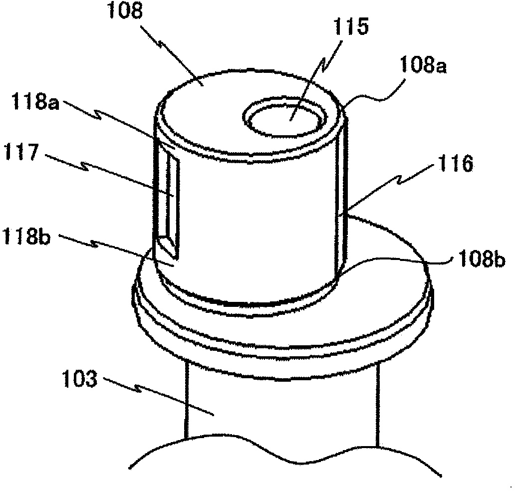
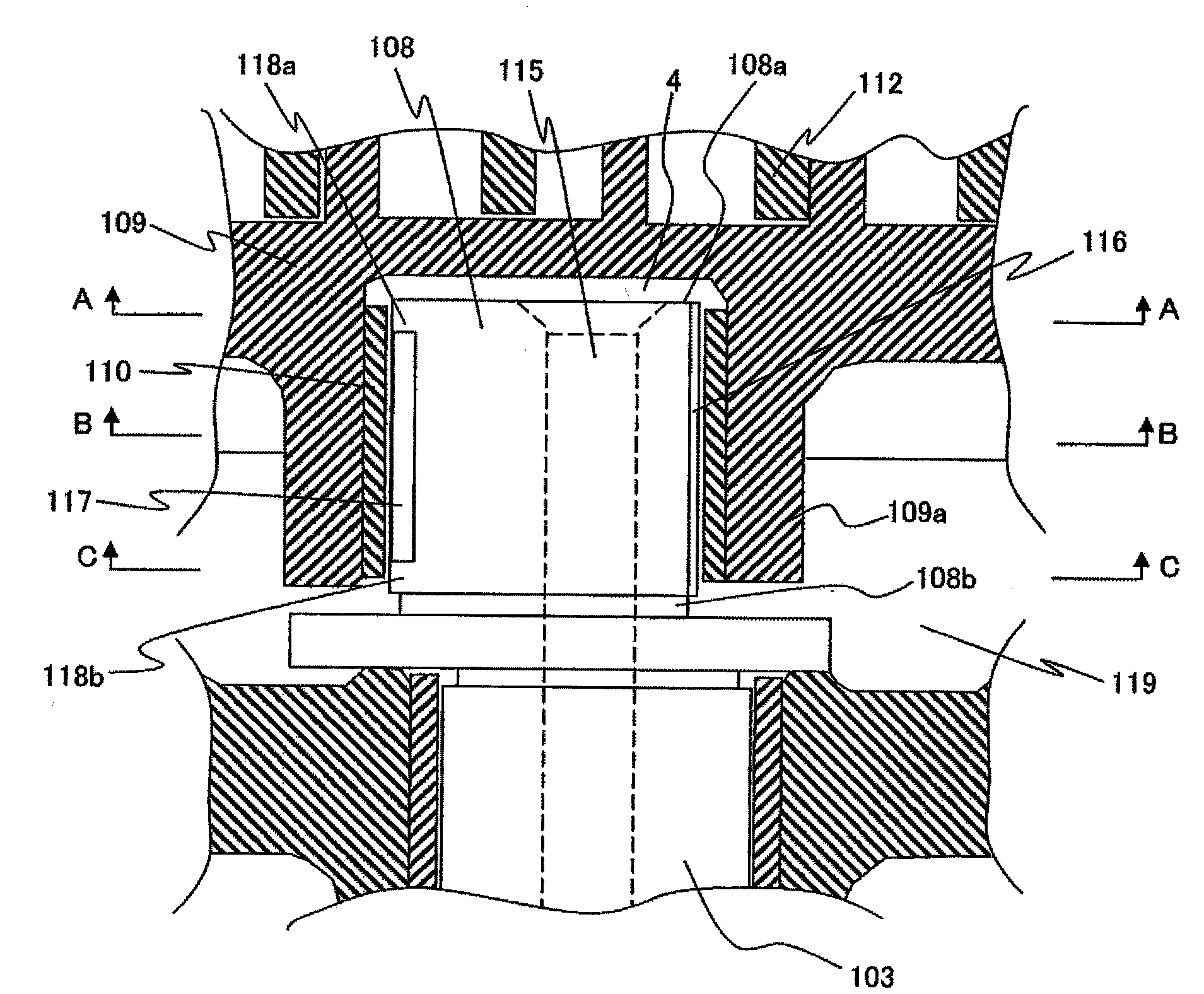
A scroll compressor equipped with: a stationary scroll (112); a rotating scroll (109); a crankshaft (103) at the end of which is an eccentric part (108); an oil supply hole (115) that penetrates the interior of the crankshaft in the axial direction and has an aperture part at the end face of the eccentric part; a rotating sliding bearing (110) that is provided on the rotating scroll, and engages the eccentric part and slides; and an oil supply passage (116) provided at the outer circumference of the eccentric part. The scroll compressor is constructed such that the interval between the eccentric part and the rotating sliding bearing is lubricated by means of lubricating oil supplied from the oil supply hole. A loss reduction groove (117) is provided separately from the oil supply passage at the outer circumference of the eccentric part in the axial direction, and seal parts (118a, 118b) are provided on the eccentric part end-face side and / or the eccentric part base side of this loss reduction groove. Thus, the shear resistance of the oil film due to the lubricating oil present between the outer circumferential surface of the eccentric part of the crankshaft and the inner circumferential surface of the rotating sliding bearing can be reduced, and bearing loss during fluid lubrication can be reduced.

Description

technical field [0001] The present invention relates to a scroll compressor used in a refrigerating and air-conditioning apparatus, and more particularly, to a scroll compressor in which an orbiting slide bearing is provided on an orbiting scroll to engage and slide with an eccentric portion of a crankshaft. Background technique [0002] A scroll compressor is a compressor that compresses gas such as a refrigerant by relatively orbiting two scroll members having a helical tooth shape. Generally, the other movable orbiting scroll is configured to orbit with respect to the fixed scroll constrained by screws, welding, or the like. In many cases, a mechanism is adopted in which an orbiting slide bearing is provided on the orbiting scroll to engage and slide with the eccentric portion of the crankshaft, and the eccentric portion of the crankshaft and the orbiting sliding bearing slide with lubricating oil while the crank The vibrating rotational motion of the shaft is transmitte...

Claims


Application Information

Patent Timeline
IPC IPC(8): F04C18/02
CPCF04C18/0215F04C29/023F04C29/0057F04C2240/54F04C18/02F04C29/02
Inventor 小山田具永柳濑裕一小山昌喜佐藤英治大野耕作
Owner HITACHI JOHNSON CONTROLS AIR CONDITIONING INC
Learn More