Linear actuator

A linear motion and drive technology, applied in the direction of electric components, electrical components, electromechanical devices, etc., can solve problems such as limiting positional relationships, and achieve the effect of easy and simple assembly

Inactive Publication Date: 2014-01-08
SHINKO ELECTRIC CO LTD
View PDF10 Cites 5 Cited by
  • Summary
  • Abstract
  • Description
  • Claims
  • Application Information

AI Technical Summary

Problems solved by technology

Thus, the positional relationship between the inner

Method used


Image

  • Linear actuator
  • Linear actuator
  • Linear actuator

Examples


no. 1 Embodiment approach

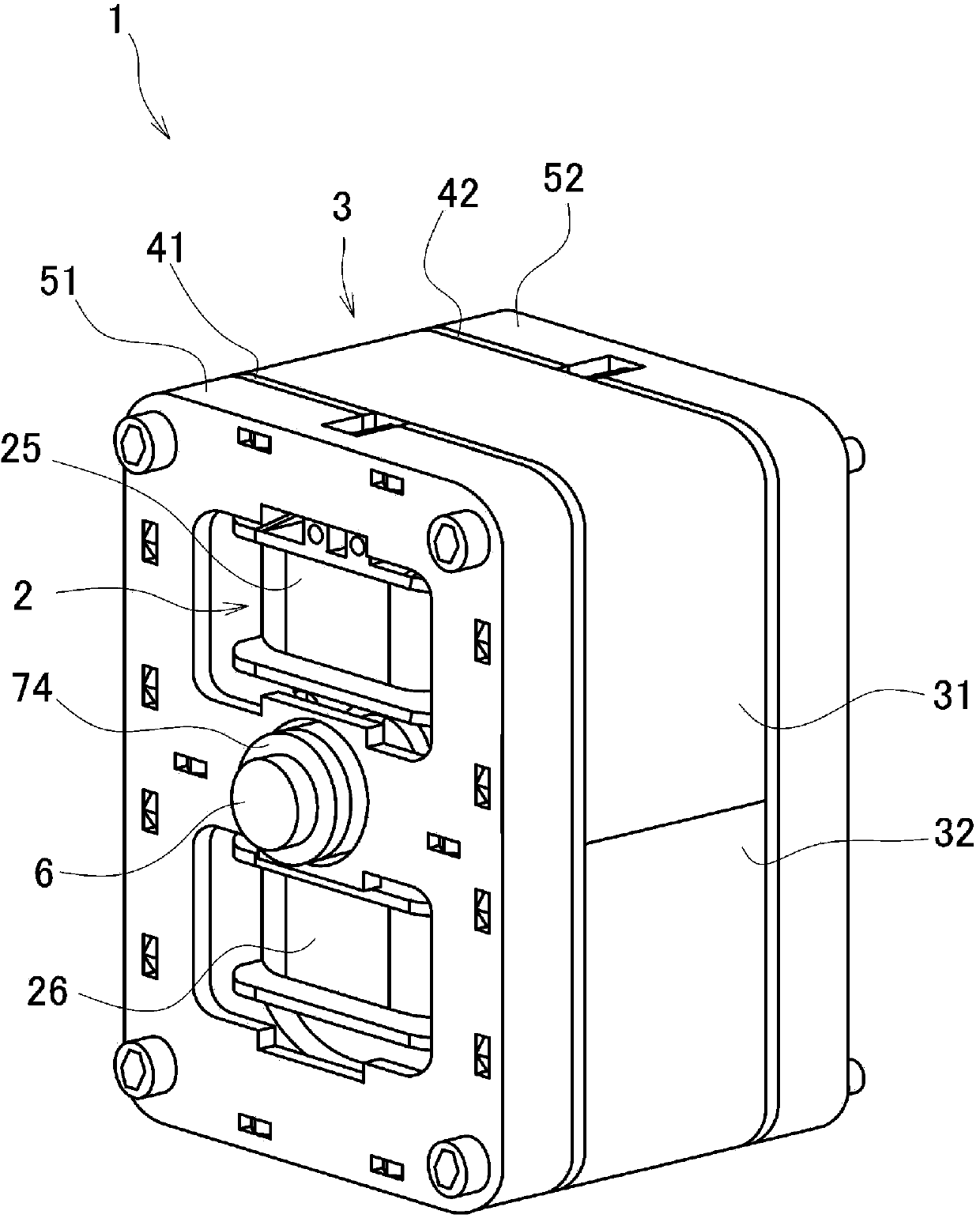
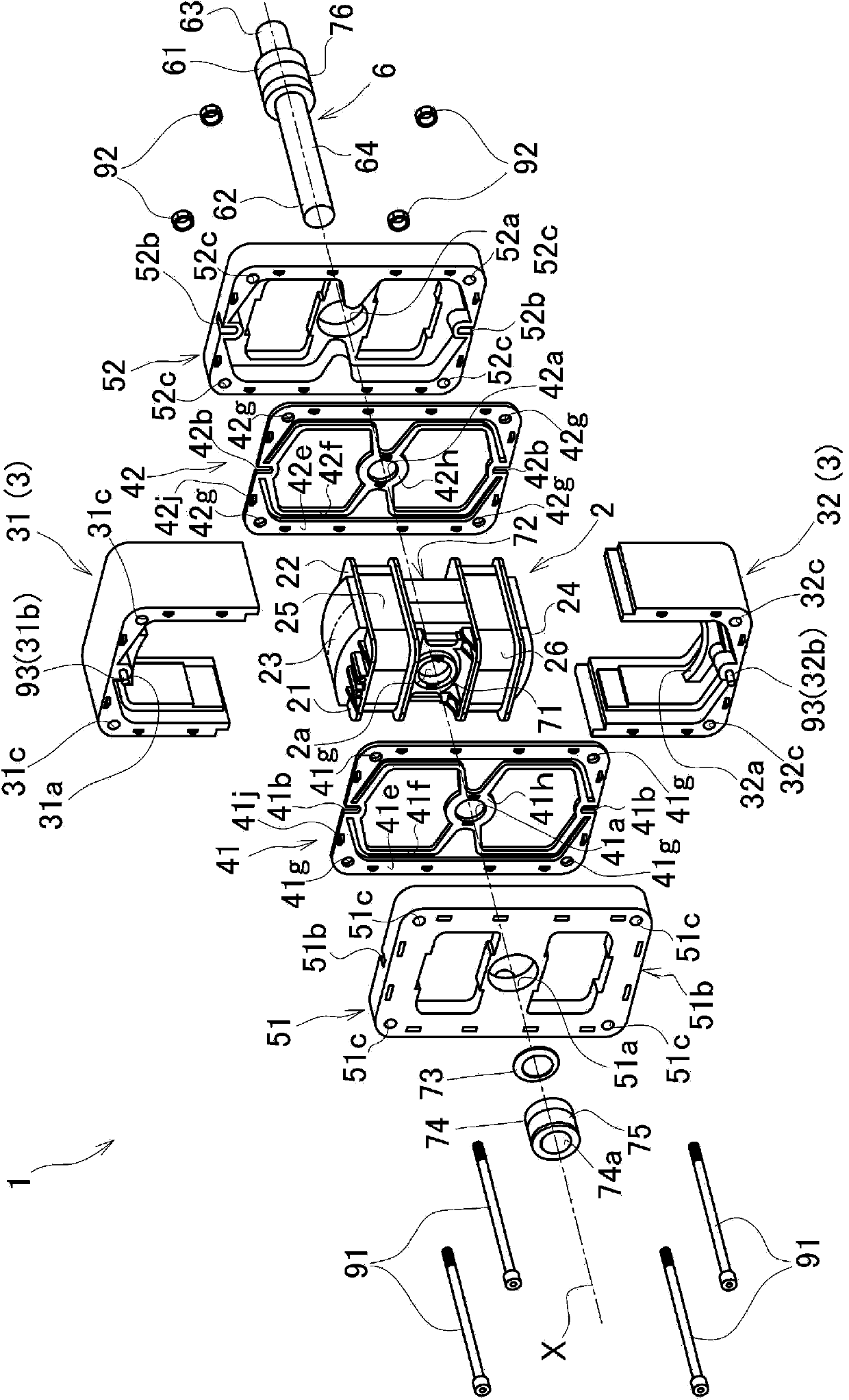
[0063] Such as figure 1 As shown, the linear motion actuator of this embodiment is generally composed of an inner core 2 provided inside, an outer core 3 provided on the outer periphery of the inner core 2 so as to have the same axis as the inner core 2, and the above-mentioned axis. The shaft 6, a pair of leaf springs 41, 42 supporting the outer core 3 on the outer periphery of the shaft 6, and stopper members 51, 52 respectively provided in the front-rear direction of the leaf springs 41, 42 are constituted.

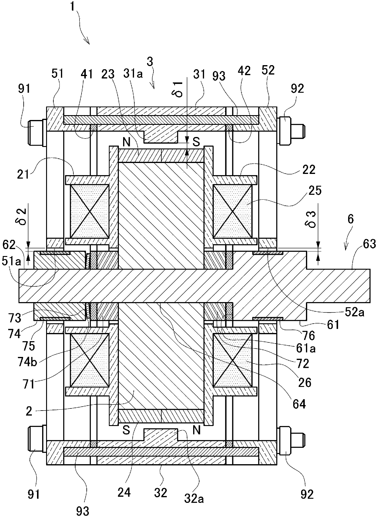
[0064] use figure 2 The central cross-sectional view shown further details the structure.

[0065] The shaft 6 is formed in a cylindrical shape extending from the rear end portion 63 on the right side in the figure toward the top end portion 62 on the left side in the figure, and the shaft 6 has a large diameter portion 61 formed on the right side in the figure relative to the center in the longitudinal direction. .

[0066] A portion from the end surface 61 a of ...

no. 2 Embodiment approach

[0146] Figure 12 It is a figure which shows the sectional view of the linear motion actuator 101 which concerns on the 2nd Embodiment of this invention, and the same code|symbol is attached|subjected to the part common to 1st Embodiment.

[0147]In this embodiment, compared with the case of the first embodiment, the number of caulking parts formed in the inner core 102, spacers 171, 172, leaf springs 141, 142, outer core 103, and stopper members 151, 152 is reduced. . Therefore, there is an advantage that the yield at the time of processing improves.

[0148] The specific positional relationship of the riveting part is as follows: Figure 13 As shown, between the inner core 102, the spacers 171, 172, and the leaf springs 141, 142 function as engaging portions, one riveting portion 102k1 is provided near each of the through holes 102a, 171a, 172a, 141a, and 142a. , 171k1, 141k1, 142k1.

[0149] In this embodiment, the inner diameter D6 to the inner diameter D10 of each thr...

no. 3 Embodiment approach

[0155] Figure 14 It is a diagram showing an exploded perspective view of a linear motion driver 201 according to a third embodiment of the present invention, and the same reference numerals are attached to the parts common to the first embodiment and the second embodiment.

[0156] In the present embodiment, the permanent magnets 223 and 224 are formed into flat plates based on the structure of the first embodiment, and the inner core 202 and the core covers 221 and 222 for mounting the permanent magnets 223 and 224 are changed to be compatible with the permanent magnet 223. , 224 corresponds to the shape. In addition, the magnetic pole portions 231 a and 232 a facing the permanent magnets 223 and 224 also have flat surfaces corresponding to the permanent magnets 223 and 224 .

[0157] Forming the permanent magnets 223 and 224 in flat form as described above facilitates the processing of the permanent magnets 223 and 224 and reduces the number of parts removed during process...


PUM


Abstract

Provided is a linear actuator, which does not generate a positional shift between an inner core and an outer core, has stable characteristics, and is easily assembled. This linear actuator is provided with an inner core (2), and an outer core (3), which is provided outside of the inner core (2) in the radius direction of the inner core, while being supported by means of a pair of plate springs (41, 42). Permanent magnets (23, 24) are provided on one core out of the inner core (2) and the outer core (3), and magnetic pole sections (31a, 32a) are formed on the other core out of the inner core (2) and the outer core (3), said magnetic pole sections facing the permanent magnets (23, 24) with a predetermined gap therebetween. Spacers (71, 72) are respectively provided between the inner core (2) and the plate springs (41, 42), contact portions are configured by bringing the facing surfaces into contact with each other in the axis direction, said facing surfaces being those of the spacers (71, 72) and the inner core (2), and those of the spacers (71, 72) and the plate springs (41, 42) adjacent to the spacers (71, 72). A plurality of engaging sections configured of recessed portions and protruding portions are provided on each of the contact portions.

Description

technical field [0001] The present invention relates to a linear motion actuator provided with a leaf spring that supports an inner core and an outer core provided radially inwardly and outwardly so as to have the same axial center, and elastically supports the outer core so as to be able to move relative to the outer core. The inner core reciprocates axially. Background technique [0002] Conventionally, various types of linear motion actuators are known as linear motion actuators that reciprocate a movable element relative to a stator in one direction under the action of magnetism. Among them, a linear motion driver having a structure shown in Patent Document 1 below is also known. [0003] This linear motion driver is a type of linear motion driver that arranges the movable element outside the stator and is called an outer rotor type. The outer side of the inner core, and the permanent magnet is arranged on the outer side of the inner core, and the magnetic pole part is...

Claims


Application Information

Patent Timeline
IPC IPC(8): H02K33/16
CPCH02K41/035H02K33/16H02K33/18
Inventor 中川洋藤井隆良福永崇酒井靖裕尾上孝志
Owner SHINKO ELECTRIC CO LTD
Why Eureka
Try Eureka