Method for preventing slipping of lower belt of blast furnace groove

A belt slippage and blast furnace slot technology, applied in the conveyor control device, conveyor objects, transportation and packaging, etc., can solve the problems of the relative displacement of the belt and the driving pulley, the complex detection of the device, and the incomplete use, and achieve the failure rate. Low, simple device effect

Active Publication Date: 2014-01-15
SHANGHAI MEISHAN IRON & STEEL CO LTD
View PDF5 Cites 4 Cited by
  • Summary
  • Abstract
  • Description
  • Claims
  • Application Information

AI Technical Summary

Problems solved by technology

[0003] In the raw material conveying system under the blast furnace trough, when the raw materials from the weighing hopper are unloaded on the belt, if the gate unloading angle is not designed properly or the gate opening time interval is not well controlled, it is easy to cause all the raw materials to fall on the belt at once. As a result, the belt is crushed to death, and there is a relative displacement between the belt and the driving wheel. Once the relative displacement between the belt and the driving wheel is commonly known as slipping, the consequences will be very serious, ranging from abrasion of the rubber on the surface of the driving wheel to serious damage. Such accidents abound. It is not that these belt systems lack slip detection devices. The reason is that there are two factors in the current method that lead to incomplete use. 1. The device detection is too complicated, and the technology involved has adopted speed measurement The detection methods of generators and rotary encoders, as well as multi-functional integrated devices, these methods are used in belt systems, and because of the harsh environment of use, the failure rate of this detection system itself is very high, so it often results in these After the detection device fails, it is habitual not to carry out maintenance, resulting in incomplete detection function, resulting in accidents due to insufficient detection and weak preventive measures
2. When the device starts protection, the belt will be stopped immediately in the first reaction. Although there is an interlock protection for stopping the belt, the time difference between the actions of gates and other on-site equipment will lead to the expansion of the accident, because when the device starts protection, the belt conveyor will be stopped immediately. However, because the material of the gate is still being unloaded, the belt is further crushed to death. Although there is no slippage, the accident handling of the pressing material will greatly delay production.

Method used


Image

  • Method for preventing slipping of lower belt of blast furnace groove

Examples


Embodiment Construction

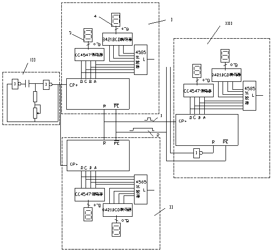
[0013] In order to deepen the understanding of the present invention, below in conjunction with appendix figure 1 The present invention will be further described.

[0014] When the belt is out, the control system sends a belt running signal "1" that is figure 1 The operation signal of the control technology device output by the central 2 centralized control center is sent to the speed detection device. This signal is sent to the PE terminal in the device. The function of the high potential of this terminal is to make the 40192 counter immediately figure 1 I, II, and IIII are counted. When the PE terminal is set to "1", the ring oscillator is figure 1 Middle III starts pulse counting according to the set frequency. If the set pulse interval is 0.1 second, then a clock counting with 0.1 second as the unit is formed. Only when the device is running, the device will work. The accumulated time is output through the A, B, C, and D terminals of the 40192 counting module, and all th...


PUM


Abstract

The invention relates to a method for preventing slipping of a lower belt of a blast furnace groove. The method for preventing slipping of the lower belt of the blast furnace groove is characterized in that the method comprises the steps that (1) the speed of the belt is detected; (2) the output of a device in the field is controlled and then the speed of the belt is detected, wherein probes, namely high-speed proximity switches, of a metal induction device fixed on a driven roller and of a detection device mainly serve as signal sources of a speed detection device. The method for preventing slipping of the lower belt of the blast furnace groove has the advantages that equipment is simple, the failure rate is low, and normal production can not be delayed.

Description

technical field [0001] The invention relates to blast furnace raw material control technology, which is a technology to prevent the belt from being crushed to death due to the sudden discharge of the unloading hopper in the raw material belt system under the blast furnace tank. [0002] slippery method. Background technique [0003] In the raw material conveying system under the blast furnace trough, when the raw materials from the weighing hopper are unloaded on the belt, if the gate unloading angle is not designed properly or the gate opening time interval is not well controlled, it is easy to cause all the raw materials to fall on the belt at once. As a result, the belt is crushed to death, and there is a relative displacement between the belt and the driving wheel. Once the relative displacement between the belt and the driving wheel is commonly known as slipping, the consequences will be very serious, ranging from abrasion of the rubber on the surface of the driving wh...

Claims


Application Information

Patent Timeline
Patent Type & Authority Applications(China)
IPC IPC(8): B65G43/04
Inventor 季益龙吴建明
Owner SHANGHAI MEISHAN IRON & STEEL CO LTD
Why Eureka
Try Eureka