Protective door device and sealing strip sawing machine

A technology for protective doors and sawing machines, which is applied to door/window fittings, the arrangement of wing sashes, power control mechanisms, etc., can solve the problems of large areas of protective doors, difficulty in meeting operation needs, affecting operating space, etc., to improve safety. Sex, fast and stable action, easy to use and operate

Active Publication Date: 2014-01-15
NINGBO MINTH AUTOMOTIVE PARTS RES&DEV CO LTD
View PDF6 Cites 6 Cited by
  • Summary
  • Abstract
  • Description
  • Claims
  • Application Information

AI Technical Summary

Problems solved by technology

Since the protective door needs to accommodate the upper body of the operator and the workpiece to enter and exit conveniently, the protective door needs a large area; the traditional revolving door that rotates around the door shaft, whether it is a single door or a symmetrical double door, will seriously affect the operating space; the traditional The sliding door that moves horizontally requires a space to accommodate the sliding door, and the opening area is only half of the operating surface of the machining equipment at most, which is often difficult to meet the operating needs

Method used


Image

  • Protective door device and sealing strip sawing machine
  • Protective door device and sealing strip sawing machine
  • Protective door device and sealing strip sawing machine

Examples


Embodiment 1

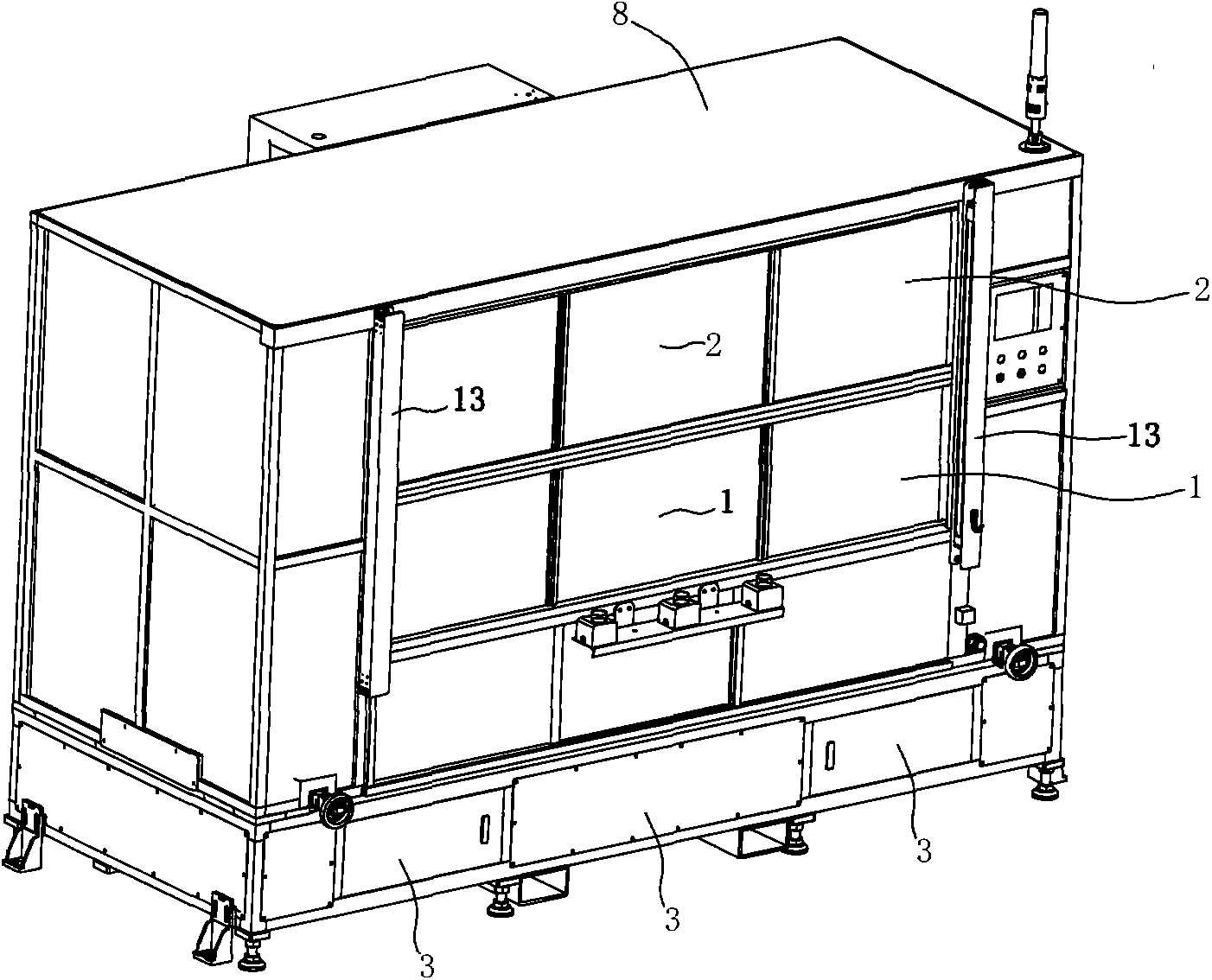
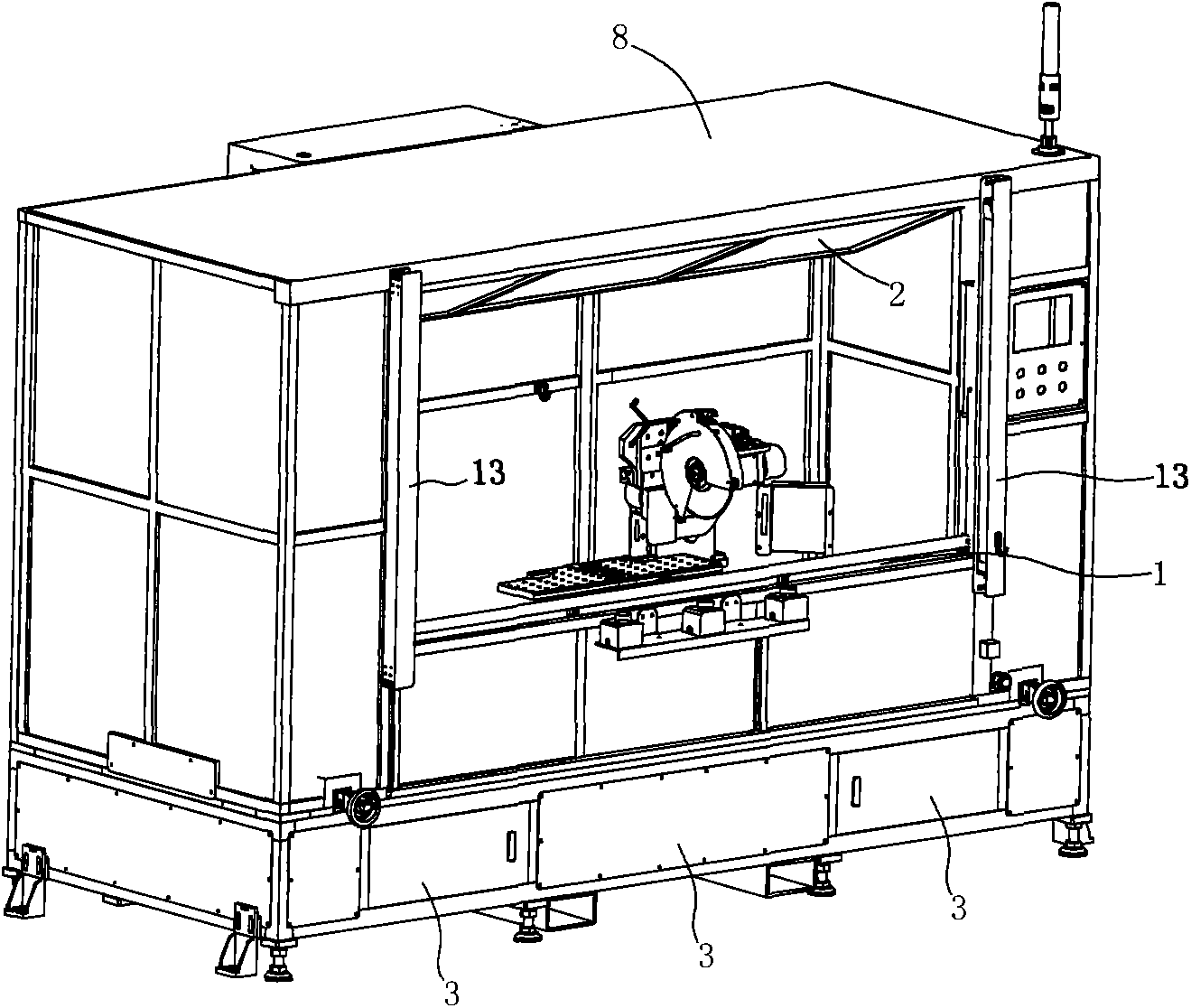
[0030] Such as image 3 , Figure 4 As shown, the sliding door drive cylinder 4 is a single cylinder located in the middle of the sliding door 1, the cylinder is fixed on the machining device frame, and the 11 ends of the piston rod are fixedly connected with the 1 frame of the sliding door. Sliding door 1 two side doorframes are provided with guide rail bar 9 respectively, and every side guide rail bar 9 is provided with a slide block 10 at least, is good with every side setting two slide blocks 10, and slide block 10 is fixedly connected with sliding door 1. The rotary door drive cylinder 5 is arranged as two cylinders, which are symmetrically arranged on the near two sides of the rotary door 2 . Such as image 3 , Figure 4 As shown, among them, image 3 In the closed state of the protective door, Figure 4 It is in the open state of the protective door. in addition, Figure 7 It is a side view of the open state of the protective door of this embodiment.

Embodiment 2

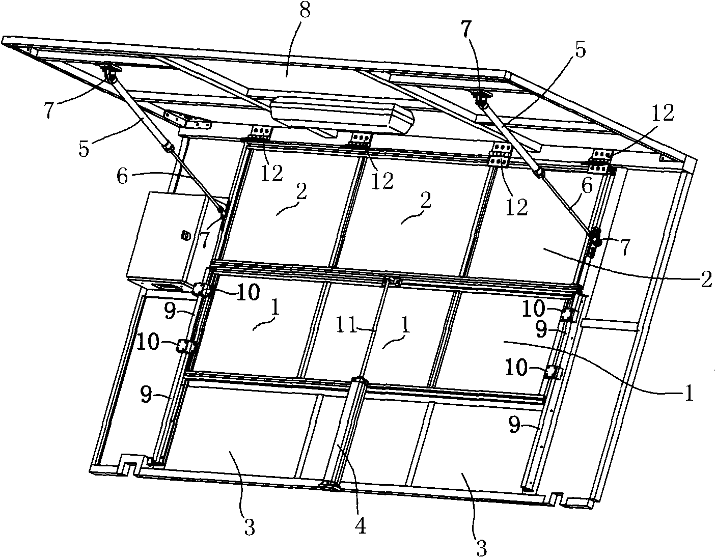
[0032] Such as Figure 5 , Image 6 As shown, the sliding door 1 two side doorframes are provided with guide rail rods 9 respectively, and each side guide rail rod 9 is provided with at least one slide block 10, preferably two slide blocks 10 are set on each side, and the slide block 10 is fixedly connected with the sliding door 1. Sliding door drive cylinder 4 is 2, is arranged on sliding door 1 two side door frames tops respectively, and its piston rod 11 lower ends are fixedly connected with slide block 10. The revolving door drive cylinder 5 is a single cylinder, located in the middle of the revolving door 2, suitable for being installed between the middle frame 15 of the revolving door 2 and the middle frame 16 of the ceiling 8. Such as Figure 5 , Image 6 As shown, among them, Figure 5 In the closed state of the protective door, Image 6 It is in the open state of the protective door. in addition, Figure 8 It is a side view of the open state of the protective d...


PUM


Abstract

A protective door device is located on an operative surface of machining equipment and comprises a moving door (1) capable of being moved up and down and a rotating door (2) capable of rotating along the upper edge of the operative surface, the moving door (1) and the rotating door (2) are driven by a moving door drive air cylinder (4) and a rotating door drive air cylinder (5) respectively, the rotating door drive air cylinder (5) is obliquely installed between a ceiling (8) and the rotating door (2), and the bottom end of the rotating door drive air cylinder (5) or the outer end of a piston rod (6) of the rotating door drive air cylinder (5) is fixedly connected with the ceiling (8) or the rotating door (2) respectively through a hinge pair (7). When the moving door (1) is located on the upper limitation position, the rotating door (2) is located at a vertical position, the lower edge of the rotating door (2) makes contact with the upper edge of the moving door (1), and the protective door device is in a closed state; when the moving door (1) is located on the lower limitation position, the rotating door (2) is located at a limit position of a tilt angle which swings inwards, and the protective door device is in an open limit state.

Description

technical field [0001] The invention relates to a protective door device suitable for machining equipment, and also relates to a sawing machine used for sawing sealing strips of automobiles. Background technique [0002] The safety of machining equipment is of paramount importance. At present, the machining equipment is generally equipped with a protective door device, which is opened when loading and unloading, and closed when starting to process. Since the protective door needs to accommodate the upper body of the operator and the workpiece to enter and exit conveniently, the protective door needs a large area; the traditional revolving door that rotates around the door shaft, whether it is a single door or a symmetrical double door, will seriously affect the operating space; the traditional A sliding door that moves horizontally requires a space next to the sliding door to accommodate the sliding door, and the opening area is at most only half of the operating surface of...

Claims


Application Information

Patent Timeline
Patent Type & Authority Applications(China)
IPC IPC(8): E06B3/44E06B3/36E05F15/04E05F15/08B23Q11/08B26D7/22E05F15/53E05F15/57
Inventor 高志文夏智慧姚必敬张满江
Owner NINGBO MINTH AUTOMOTIVE PARTS RES&DEV CO LTD
Why Eureka
Try Eureka