
Self-centering pneumatic tight-supporting type clamp for disc parts

A disc-type parts, self-centering technology, applied in the field of disc-type parts self-centering pneumatic support clamps, can solve the problems of unrepairable equipment, long auxiliary time, affecting the machining accuracy of parts, etc., to improve maintainability, The action is fast, stable, and reliable.

Pending Publication Date: 2022-07-05
SHENYANG INST OF TECH
View PDF0 Cites 0 Cited by
  • Summary
  • Abstract
  • Description
  • Claims
  • Application Information

AI Technical Summary

Problems solved by technology

[0002] The common fixture positioning form is the form of two pins on one side, and the manual pressing plate is used for pressing. It is imperative to change the traditional manual work. In order to better cooperate with the CNC machine tools with a relatively high degree of automation, the traditional clamping form takes a long time to assist. Invisibly increases non-value-added costs, which cannot meet the needs of rapid development of enterprises
[0003] At the same time, the traditional clamping method has the problem of affecting the processing surface or hole. Therefore, repeated clamping is required, which causes a certain installation error and affects the processing accuracy of the parts.
[0004] In the process of traditional fixture design, the maintainability of the fixture and the environmental protection of the working medium are often neglected, which may easily cause the equipment to be irreparable, thus causing a large waste of fixtures
[0005] In view of the problem that manual clamping affects the processing efficiency and cannot meet the development needs of intelligent manufacturing, combined with the characteristics that disc parts usually use the middle hole as the positioning feature, it is urgent to realize a self-centering of disc parts on the basis of the original positioning scheme Quick and efficient clamping design of pneumatic clamping fixture

Method used


Image

  • Self-centering pneumatic tight-supporting type clamp for disc parts
  • Self-centering pneumatic tight-supporting type clamp for disc parts
  • Self-centering pneumatic tight-supporting type clamp for disc parts

Examples


Embodiment Construction

[0035] The technical solutions in the embodiments of the present invention will be clearly and completely described below with reference to the accompanying drawings in the embodiments of the present invention. Obviously, the described embodiments are only a part of the embodiments of the present invention, not all of the embodiments. The embodiments of the present invention, and all other embodiments obtained by those of ordinary skill in the art without creative work, fall within the protection scope of the present invention.

[0036] see Figure 1-10 , the present invention provides a kind of technical scheme:

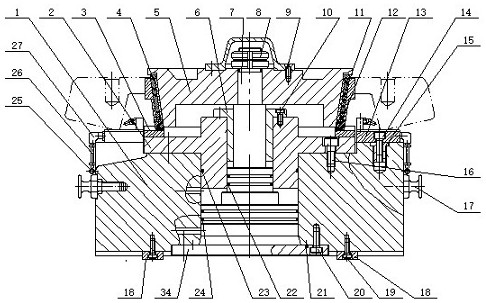
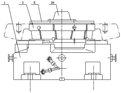
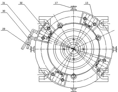
[0037] A self-centering pneumatic support clamp for disc parts, comprising a clamping body 1, a disc seat 2 is arranged above the clamping body 1, fixed with the clamping body 1 by hexagon socket screws 16, and a spring expansion sleeve 3 is arranged above the disc seat 2 There are three sets of positioning blocks 13 above the clamping body 1, a sealing cover 34 is...


PUM


Abstract

A self-centering pneumatic tight-supporting type clamp for disc parts comprises a clamp body, a disc seat is arranged above the clamp body, a spring expansion sleeve is arranged above the disc seat, cutting grooves are distributed in the conical surface of the spring expansion sleeve in an up-down alternating mode, seals are arranged at the cutting grooves of the spring expansion sleeve, scrap iron is prevented from entering the conical surface, three sets of positioning blocks are arranged above the clamp body, and nozzle assemblies are arranged above the positioning blocks. A sealing cover is arranged on the lower portion of the middle of the clamp body, a piston rod shaft is arranged in the middle of the clamp body, a sleeve and an outer cone are arranged above the piston rod shaft, the outer cone moves downwards under the action of an electromagnetic valve and expands a spring expansion sleeve at the same time, and two sets of positioning keys are arranged below the clamp body to achieve guiding. The clamp has the beneficial effects that air is adopted as a working medium, environment friendliness is achieved, the outer cone is adopted to drive the spring expansion sleeve to tightly support a workpiece, action is rapid, a multi-dimensional sealing device is adopted, scrap iron is prevented from entering the conical surface of the spring expansion sleeve, the positioning block and the clamp body are additionally connected through the threaded sleeve, and the maintainability of the clamp is improved.

Description

technical field [0001] The invention relates to the field of intelligent manufacturing and processing, in particular to a self-centering pneumatic clamping clamp for disc parts. Background technique [0002] The common fixture positioning form is the form of two pins on one side, and the manual pressing plate is used for pressing. It is imperative to change the traditional manual operation. In order to better cooperate with the CNC machine tools with a relatively high degree of automation, the traditional clamping form has a long auxiliary time. Invisibly increased non-value-added costs, can not meet the needs of the rapid development of enterprises. [0003] At the same time, using the traditional clamping plate form has the problem of affecting the processing surface or holes. Therefore, repeated clamping is required, resulting in a certain installation error and affecting the machining accuracy of the parts. [0004] In the process of traditional fixture design, the main...

Claims


Application Information

Patent Timeline
Patent Type & Authority Applications(China)
IPC IPC(8): B23Q3/08
CPCB23Q3/08B23Q2703/04Y02P70/10
Inventor 穆德敏赵元刘业峰张丽丽姜雨歆王瑞洋尚佳雨
Owner SHENYANG INST OF TECH
Learn More