Fastener and manufacturing method thereof

A technology of fasteners and fastener clips, which is applied in the direction of connecting components, building structures, and detachable fasteners for friction clamping, etc., can solve the problems of easy loosening, general anti-skid effect, and low strength.

Inactive Publication Date: 2014-01-15
河北立新科技有限公司
View PDF8 Cites 4 Cited by
  • Summary
  • Abstract
  • Description
  • Claims
  • Application Information

AI Technical Summary

Problems solved by technology

However, the processing of the existing steel plate fasteners is cumbersome, the weight is large, and the production links are many, which leads to slow production speed, especially its low strength.
Since the fastener uses a triangular plate-shaped center plate, the fitting surface with the clamped object is not large enough, resulting in limited friction with the clamped object, and the anti-skid effect is general; and the rotation between the cover plate and the base The connection part is easy to loosen during use
[0007] The common disadvantage of the prior art fasteners including the above fasteners is that their fastening strength is not high, which is mainly due to the insufficient strength of the pin connection between the cover plate and the base, and the pin connection only relies on Its own structural strength and force to provide the required fastening strength
In ord...

Method used


Image

  • Fastener and manufacturing method thereof
  • Fastener and manufacturing method thereof
  • Fastener and manufacturing method thereof

Examples


Embodiment Construction

[0124] Hereinafter, the present invention will be described in detail with reference to the drawings and examples. It should be noted that, in the case of no conflict, the features in the various embodiments of the present application may be combined or replaced with each other.

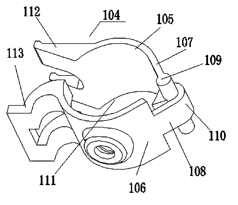
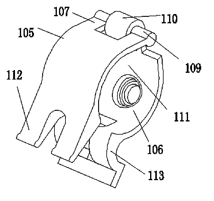
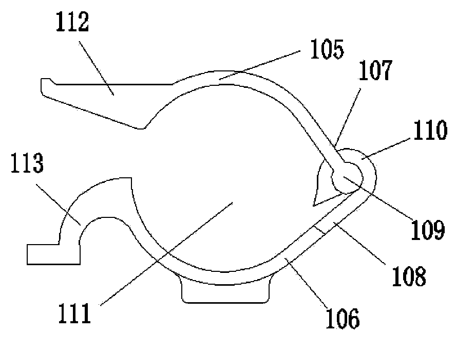
[0125] The invention provides a fastener for clamping an object, the fastener comprises a first clamping arm and a second clamping arm, the first end of the first clamping arm and the first end of the second clamping arm are connected to each other through a rotatable connection mechanism A rotatable connection forming a cavity between the first and second clamp arms for accommodating the object while clamping the object, wherein the rotatable connection mechanism includes a pin shaft and winding around the pin shaft and winding around the pin shaft a rotatable coil connected at its first end to or as part of one of the first and second clamp arms, the pin connected to the other of said first and sec...


PUM


Abstract

The invention discloses a fastener used for clamping an object. The fastener comprises a first clamping arm and a second clamping arm, wherein the first end of the first clamping arm and the first end of the second clamping arm are connected with each other in a rotating mode through a rotary connecting mechanism, and a cavity used for containing the object when the object is clamped is formed between the first clamping arm and the second clamping arm. The rotary connecting mechanism comprises a hinge pin and a winding part, wherein the winding part is wound around the hinge pin and can rotate around the hinge pin, the first end of the winding part is connected with the first clamping arm or the second clamping arm or serves as a part of the first clamping arm or the second clamping arm, the hinge pin is connected with the second clamping arm or the first clamping arm or serves as a part of the second clamping arm or the first clamping arm, and the second end of the winding part is located in the cavity and makes rubbing contact with the object when the fastener is used for clamping the object. The invention further discloses a manufacturing method of the fastener. In addition, the invention further discloses a self-locking device which can be used in the fastener for example.

Description

technical field [0001] The invention relates to the technical field of fastening devices, in particular to a fastener for clamping objects and a manufacturing method of the fastener. The fastener is, for example, a construction fastener used to build a scaffold. Background technique [0002] Fasteners, as a fastening device, are widely used in various fields for fastening, for example, they are used in the construction field to build scaffolding. In the prior art, the fastener generally includes a cover plate and a base (hereinafter collectively referred to as “clamp arms”), and a rotatable connection is formed between the cover plate and the base through a pin shaft. [0003] Existing fasteners generally include fasteners made by casting and fasteners formed by hot forging. [0004] In the cast fastener, the through hole on the cover plate for the pin shaft to pass through and the through hole on the base for the pin shaft to pass through are both formed by a perforation ...

Claims


Application Information

Patent Timeline
IPC IPC(8): F16B2/06E04G7/14E04G7/16
Inventor 周立新
Owner 河北立新科技有限公司
Why Eureka
Try Eureka