Single-edge fastening bolt

A technology for unilaterally tightening bolts and bolts, used in threaded fasteners, deformable fasteners, screws, etc., can solve the problems of many parts and slow installation speed, to ensure integrity, easy and fast installation, avoid The effect of opening weakening

Inactive Publication Date: 2014-01-15
TONGJI UNIV
View PDF16 Cites 15 Cited by
  • Summary
  • Abstract
  • Description
  • Claims
  • Application Information

AI Technical Summary

Problems solved by technology

Although this invention can realize the function of one-way fastening, because of its many parts, the installation speed is relatively slow

Method used


Image

  • Single-edge fastening bolt
  • Single-edge fastening bolt
  • Single-edge fastening bolt

Examples


Embodiment 1

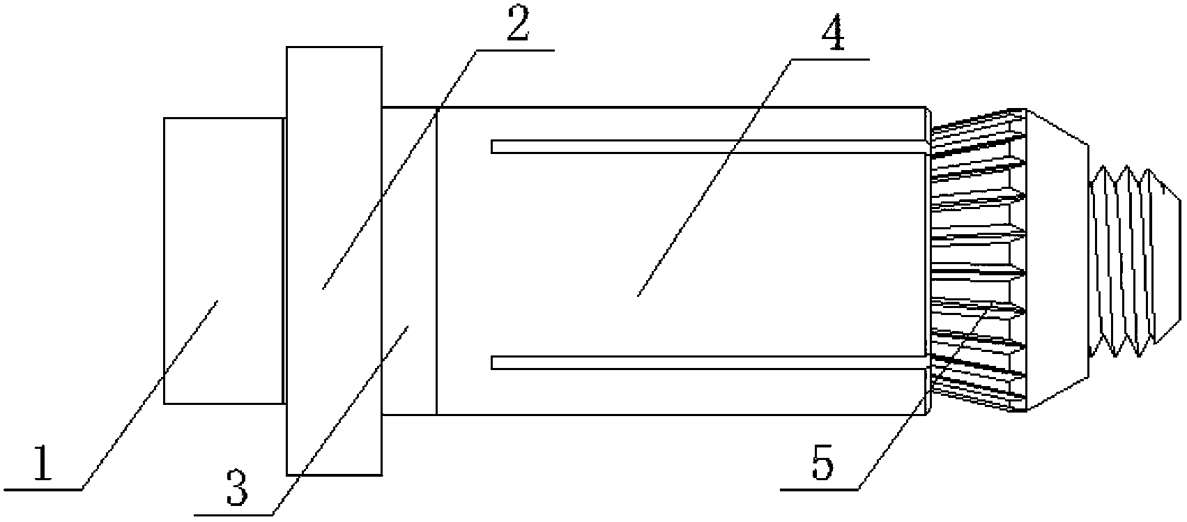
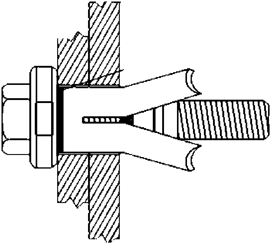
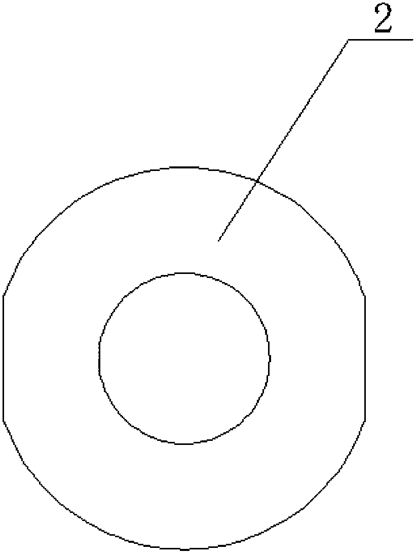
[0034] figure 1 Shown is an embodiment of the unilateral fastening bolt of the present invention. In order to solve the one-way assembly problem, the technical solution adopted in the present invention is: a conventional bolt includes a screw rod and a bolt head 1 at one end of the screw rod, and the present invention starts from the bolt head 1 on the screw rod. The head end is provided with a washer 2, a casing 4 and a cone head 5 in sequence, and a screw hole is provided on the cone head to be threadedly connected with the screw rod ( Figure 8 and Figure 9 As shown), the spacer 2, sleeve 4 and the screw are clearance fit, the outer diameter of the sleeve is larger than the inner diameter of the washer, and there are multiple axial slits on the end of the sleeve near the cone head, and the small end of the cone head snaps into the sleeve , the outer diameter of the big end of the cone head is greater than or equal to the inner diameter of the casing. Such as figure 2 A...

Embodiment 2

[0038] In Embodiment 1, the casing 4 is a cylindrical casing, and the casing can also be trumpet-shaped, square or other shapes, and the ultimate goal is to ensure that the casing 4 can be stretched by the cone head 5 . When the sleeve is trumpet-shaped, its small opening end faces the gasket 2, and its large opening end faces the cone head 5, and the outer diameter of the large end of the cone head should be greater than or equal to the maximum outer diameter of the sleeve, and the inner diameter of the gasket should be smaller than that of the sleeve. The minimum outside diameter of the tube. Compared with other shapes, it is obvious that the force of the cylindrical sleeve is more uniform when it is stretched by the cone head, and it is easier to be stretched, and the cylindrical sleeve is also more suitable for the cylindrical screw.

[0039] Because the casing 4 is gradually stretched from the cone end, the wall thickness of the casing gradually becomes thinner from the w...

Embodiment 3

[0041] In order to facilitate the locking of the casing 4 and the cone head 5 so that it cannot be rotated relative to each other, the outer surface of the cone head is set to be uneven. Theoretically, as long as enough pressure is applied to achieve a high enough friction between the sleeve and the cone, the cone with a smooth outer surface can also achieve the purpose of locking the sleeve, but obviously the friction provided by the uneven surface of the cone Higher force for better fixation. And preferably, as figure 1 As shown, in this embodiment, the outer surface of the cone head is evenly distributed with multiple rows of convex ribs, which not only increases the friction force, but also the convex ribs are easy to snap into the cracks on the casing to lock the casing.

[0042] Such as image 3 and Figure 4 As shown, the outer peripheral surface of the washer is provided with two symmetrical planes, which facilitates the use of tools to hold the washer.

[0043] In t...


PUM


Abstract

The invention provides a single-edge fastening bolt. The singe-edge fastening bolt comprises a screw and a bolt head at one end of the screw. A gasket, a sleeve and a conical head are sequentially arranged on the screw from the end of the bolt head in a sleeved mode. The conical head is provided with a screwed hole which is in threaded connection with the screw, the gasket is in clearance fit with the screw, the sleeve is also in clearance fit with the screw, the outer diameter of the sleeve is larger than the inner diameter of the gasket, a plurality of axial cracks are formed in the end, close to the conical head, of the sleeve, the smaller end of the conical head is clamped into the sleeve, and the outer diameter of the larger end of the conical head is larger than or equal to the inner diameter of the sleeve. According to the single-edge fastening bolt, on the premise that the installation speed and the node strength are not lowered, the problem that when sealed section part bolt connection is completed through a traditional method, an opening of a connected section is weakened, and the single-edge fastening bolt has the advantages that installation is convenient and quick, the requirements for sealed section part connection are met, and the integrity of the connected section is guaranteed.

Description

technical field [0001] The invention belongs to the field of component connection, in particular to a unilateral fastening bolt used for connecting two components, one of which is a closed section. Background technique [0002] The connection method of steel structure can be divided into welding, riveting and bolt connection. Welding connection is the most important connection method for steel structures. Its advantages are simple structure, no weakening of component sections, steel saving, convenient processing, easy automation, good sealing performance and high rigidity; the advantages of rivet connection are plasticity and toughness. It is better, reliable in force transmission, and easy to check in quality. It is suitable for the connection of structures directly bearing dynamic loads. The disadvantage is that the structure is complex and the amount of steel is large, so it is rarely used at present; and the bolted connection is simple because of its simple construction,...

Claims


Application Information

Patent Timeline
Patent Type & Authority Applications(China)
IPC IPC(8): F16B13/06
CPCF16B13/0858F16B29/00F16B43/001
Inventor 许炎彬李国强张龙
Owner TONGJI UNIV
Why Eureka
Try Eureka