
Mechanism for adjusting rotation directions and rotation speeds of inner ring and outer ring of rotation bearing

A technology of rotating bearing and direction of rotation, which is used in rotating bearings, rolling contact bearings, rigid supports of bearing components, etc., can solve the problems of increasing the laminar flow velocity of the fluid, reducing the shear force in the fluid, and increasing the rolling components. The effect of increasing the laminar flow velocity of the fluid, reducing the shear force, and reducing the friction loss

Inactive Publication Date: 2014-01-15
刘复建
View PDF8 Cites 2 Cited by
  • Summary
  • Abstract
  • Description
  • Claims
  • Application Information

AI Technical Summary

Problems solved by technology

[0006] The purpose of the present invention is to provide a mechanism for adjusting the rotation direction and speed of the inner ring and the outer ring of the rotating bearing to solve the problem that the rolling assembly in the traditional contact rolling bearing is prone to internal wear, so that the inner ring of the rotating bearing is in contact with the rolling assembly. The inner ring and the outer ring rotate in the opposite direction, and the linear speed of the two is equal to or nearly equal to the tangential speed of the rolling assembly, thereby reducing the sliding of the rolling assembly, increasing the rolling of the rolling assembly, and reducing the friction loss in the rolling bearing; while for non- Contact rotary bearings make the inner and outer rings of the rotary bearings in the same direction, and the linear speed of the two is equal or nearly equal, thereby increasing the laminar flow velocity of the fluid (which can be gas or liquid) and reducing the internal shear force of the fluid

Method used


Image

  • Mechanism for adjusting rotation directions and rotation speeds of inner ring and outer ring of rotation bearing
  • Mechanism for adjusting rotation directions and rotation speeds of inner ring and outer ring of rotation bearing
  • Mechanism for adjusting rotation directions and rotation speeds of inner ring and outer ring of rotation bearing

Examples


Embodiment Construction

[0084] In order to make the technical means, creative features, goals and effects achieved by the present invention easy to understand, the present invention will be further described below in conjunction with specific embodiments.

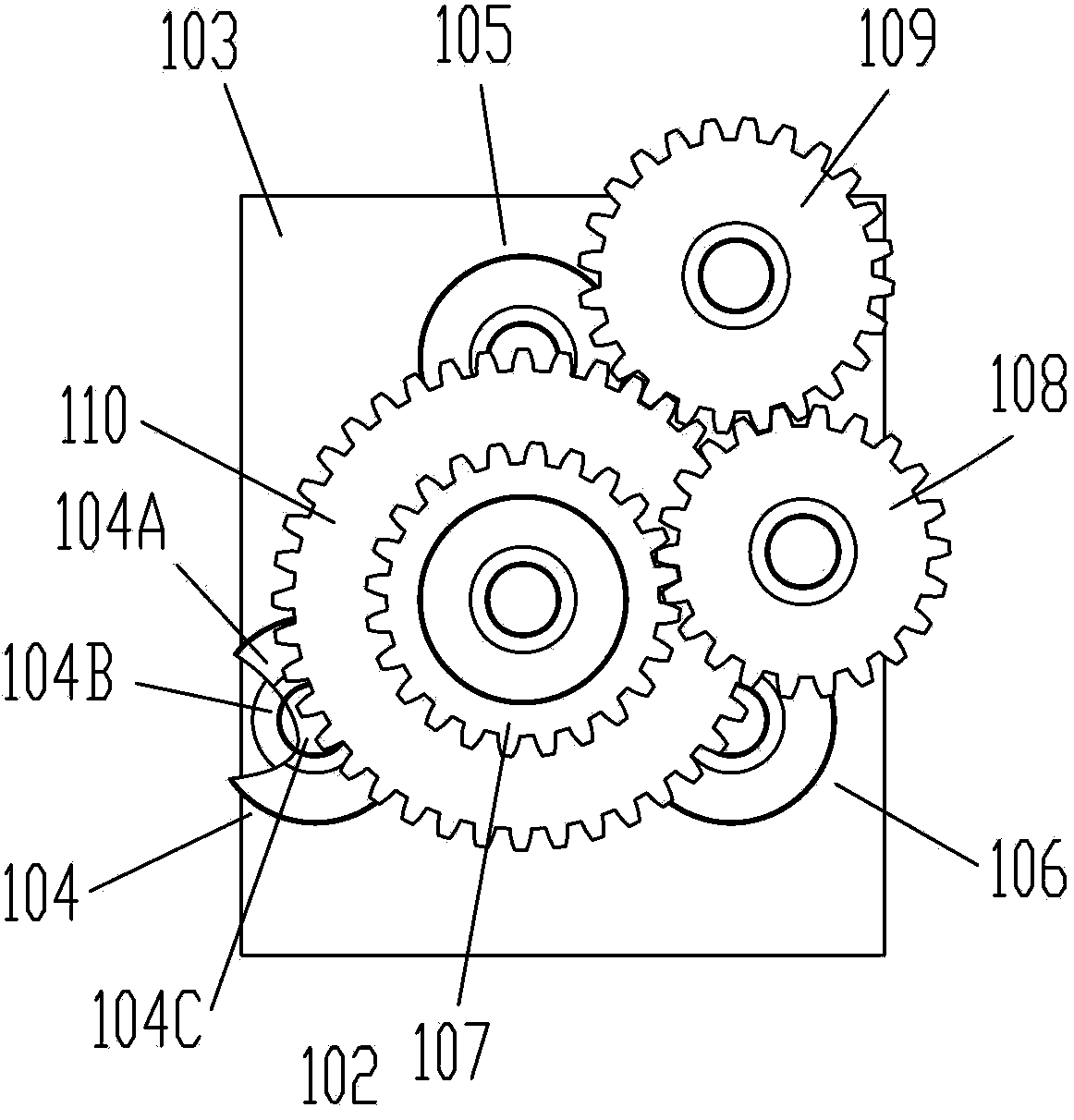
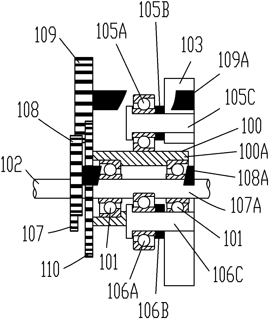
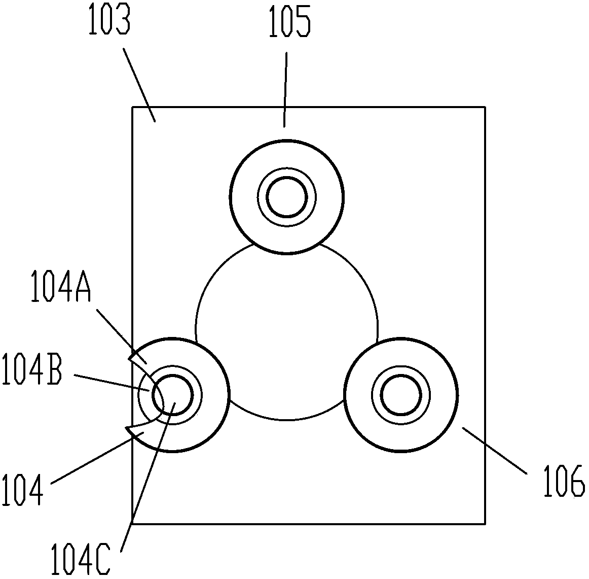
[0085] see figure 1 and figure 2 ,in figure 1 It is the front view of the combination mechanism of contact type rolling bearing and gear according to the present invention, figure 2 its section view. The combination mechanism of the contact type rotating bearing and the gear of the present invention comprises a base, a main bearing group passing through the base, a plurality of supporting rotating bearings and a transmission mechanism installed on the base around the main bearing group, the main bearing The set includes at least one rolling bearing. In the application of contact rolling bearing, it includes inner ring, outer ring and multiple rolling elements. The inner ring is connected with a shaft, and the main bearing group is equipped ...


PUM


Abstract

The present invention relates to the field of transmission mechanisms, particularly to a mechanism capable of adjusting rotation directions and rotation speeds of an inner ring and an outer ring of a rotation bearing. The mechanism comprises a base (103), a main bearing set (100,130) penetrating through the base (103), a plurality of support rotation bearing (104,105,106) installed on the base (103) and positioned on the periphery of the main bearing set (100, 130), and a transmission mechanism, wherein the main bearing set (100, 130) comprises at least a main bearing (101,131), the main bearing (101, 131) comprises an inner ring (101E, 111) and an outer ring (101A, 112), the inner ring (101E or 111) and a shaft (102) are connected, the mechanism further comprises a plurality of rolling assemblies (101D) in an application of a contact type bearing, and the mechanism further comprises a fluid (115) in an application of a non-contact type bearing. According to the present invention, the transmission mechanism is additionally arranged in the rotation bearing, such that the inner ring and the outer ring of the bearing perform proper rotation.

Description

technical field [0001] The invention relates to the field of transmission mechanisms, in particular to a mechanism capable of adjusting the rotation direction and speed of an inner ring and an outer ring of a rotating bearing. Background technique [0002] The composition of a general rotating mechanism includes: 1. Contact rotating bearings include shafts and rotating bearings, bearings include ball bearings, roller bearings or needle bearings, etc.; 2. Non-contact rotating bearings include shafts and hydraulic bearings, shafts and air bearings Wait. Under normal operating conditions, contact bearing wear problems occur more often, while in non-contact bearings due to the use of higher viscosity fluids and higher pressure gases, fluids, leak-proof gaskets and seals need to be replaced regularly. [0003] In order to maintain the rigidity and precision requirements of the rotating system, the contact between the shaft and the inner surface of the rotating bearing needs to b...

Claims


Application Information

Patent Timeline
IPC IPC(8): F16C41/00
CPCF16C19/163F16C19/54F16C33/306F16C19/00F16C19/04F16C25/00F16C32/06F16C35/04F16C35/042F16C41/00F16C41/02Y02E10/72
Inventor 刘复建
Owner 刘复建
Learn More