Electronic expansion valve

An electronic expansion valve, valve seat technology, applied in the direction of control valve, valve device, functional valve type, etc., can solve the problems of large reverse flow resistance, large radial size of valve seat 20, difficult rotation of valve needle 24, etc. The effect of reducing flow resistance, reducing axial and radial dimensions

Active Publication Date: 2014-01-15
ZHEJIANG SANHUA INTELLIGENT CONTROLS CO LTD
View PDF7 Cites 21 Cited by
  • Summary
  • Abstract
  • Description
  • Claims
  • Application Information

AI Technical Summary

Problems solved by technology

[0009] First, in the above structure, the one-way valve core 60 is set at the lower part of the valve core seat 22, and the valve needle 24 is respectively set on both sides of the valve core seat 22. When the refrigerant flows in the forward direction, due to the upward impact force of the refrigerant Larger, this requires the buffer spring inside the valve needle 24 to have a larger spring force to ensure that the valve needle 24 is sealed under high pressure conditions, and the increase of the spring force will bring a series of problems, which will increase the rotation of the valve needle 24. Difficult, it will increase the volume of the product. Generally speaking, it is quite good for the spring to be designed to withstand the refrigerant pressure of 2.5MPa and maintain the seal. It is difficult for products with this structure to maintain the seal under the refrigerant pressure of 3.5MPa.
[0010] Second, the one-way valve core 60 is installed on the bottom of the valve core seat 22, and requires the one-way valve core 60 to have a certain stroke. To the height
[0011] Third, since the one-way valve core 60 needs to be provided with a bypass flow path 70, the refrigerant needs to pass through the bypass flow path 70 during reverse flow, resulting in a relatively large reverse flow resistance; on this basis, in order to reduce the reverse flow resistance, it is necessary to The valve seat 20 has a sufficiently large diameter, which in turn leads to a larger radial dimension of the valve seat 20

Method used


Image

  • Electronic expansion valve
  • Electronic expansion valve
  • Electronic expansion valve

Examples


Embodiment Construction

[0055] The core of the present invention is to provide an electronic expansion valve. On the one hand, the structural design of the electronic expansion valve can ensure that the valve needle part can easily seal the valve core valve port under the high-pressure state of the forward flow of refrigerant, and prevent the valve needle part from being pushed by the high-pressure refrigerant. On the other hand, it can reduce the axial and radial dimensions of the valve seat and reduce the flow resistance during reverse flow.

[0056] In order to enable those skilled in the art to better understand the technical solutions of the present invention, the present invention will be further described in detail below in conjunction with the accompanying drawings and specific embodiments.

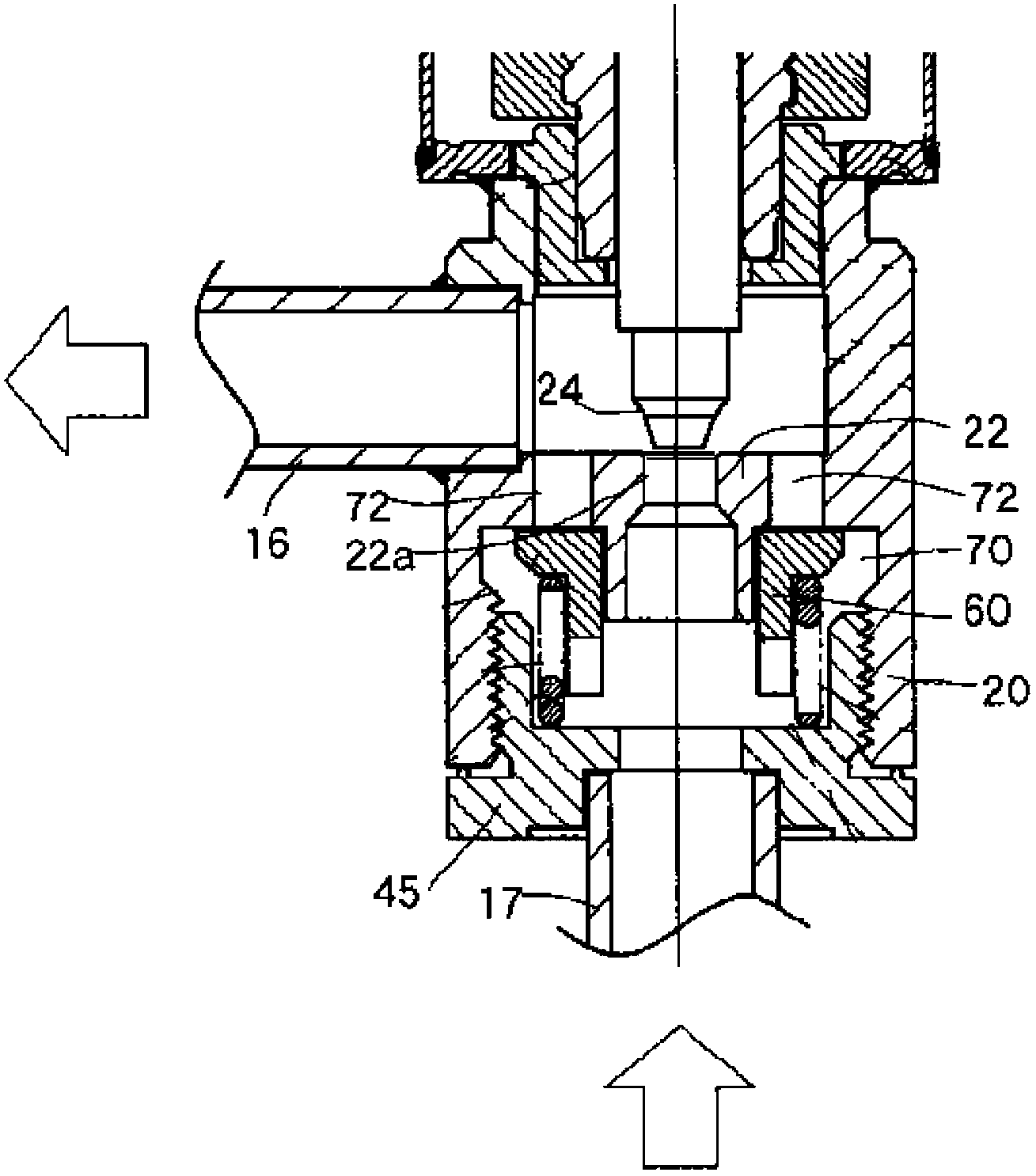
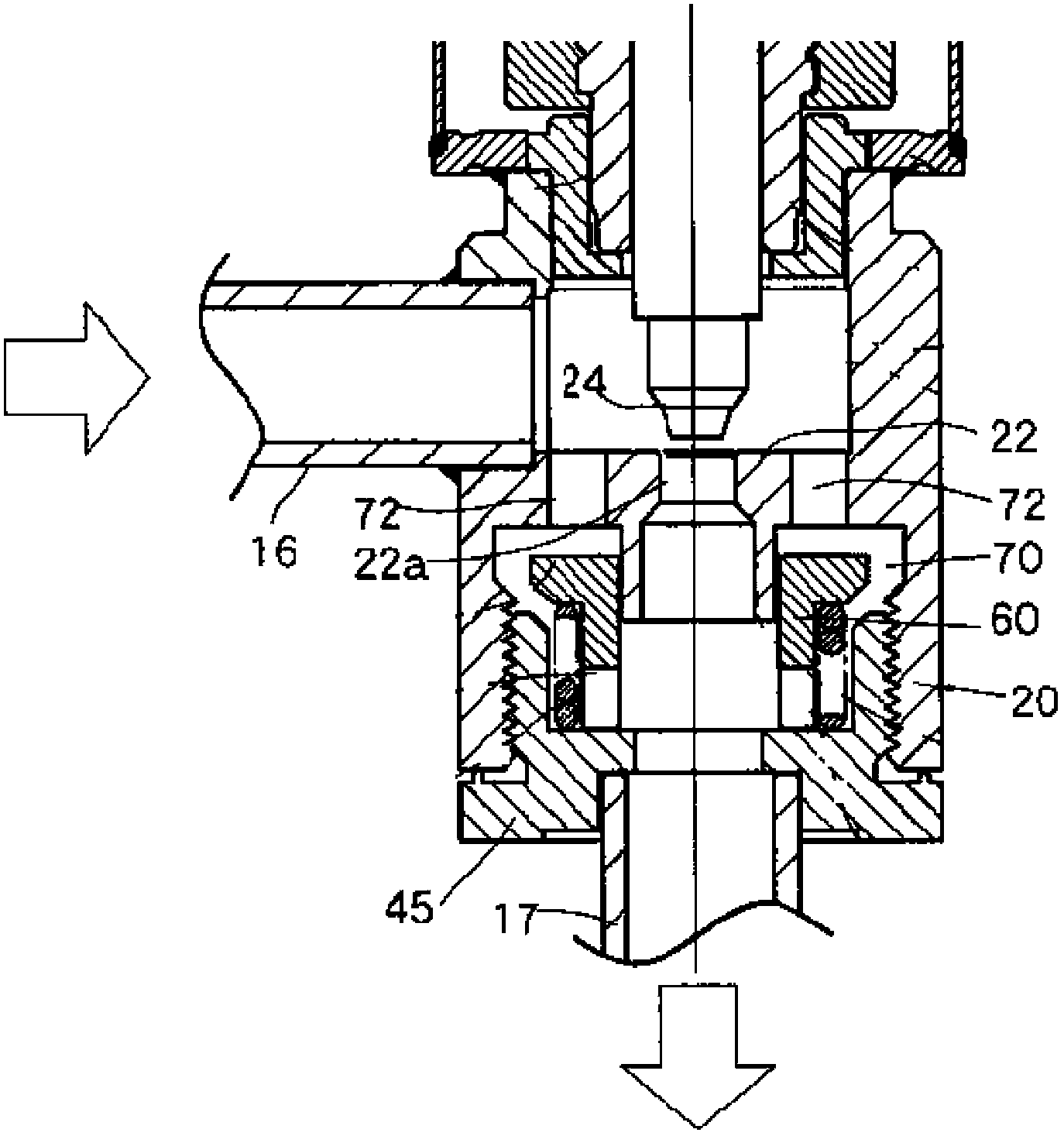
[0057] Please refer to Figure 4 and Figure 5 , Figure 4 It is a structural schematic diagram of the electronic expansion valve in the first embodiment of the present invention when the refrigerant f...


PUM


Abstract

The invention discloses an electronic expansion valve. According to the electronic expansion valve, a piston part (4) and a valve needle part (3) are located on the same side of a valve element seat (2) so that a bypass through hole (212) can be blocked by the piston part (4) when a refrigerant flows in the forward direction, the refrigerant flows to one end of a vertical connecting pipe (52) through a valve element valve port (211), and the valve needle part (3) moves in the axial direction to adjust the open degree of the valve element valve port (211); when the refrigerant flows in the backward direction, the piston part (4) moves upwards in the axial direction to open the bypass through hole (212), and the refrigerant flows to one end of a transverse connecting pipe (51) through the bypass through hole (212). According to the electronic expansion valve, on one hand, the valve element valve port can be sealed easily by the valve needle part under the high-pressure condition when the refrigerant flows in the forward direction, and the valve needle part is prevented from being ejected open by the high-pressure refrigerant; on the other hand, the axial size and radial size of a valve seat can be reduced, and flow resistance when the refrigerant flows in the backward direction is reduced.

Description

technical field [0001] The invention relates to the technical field of fluid control components, in particular to an electronic expansion valve. Background technique [0002] In the air conditioner market, due to the long distance between the indoor unit and the outdoor unit, two electronic expansion valves are used, and the two electronic expansion valves must be connected in parallel with one-way valves to maximize system efficiency. Its system schematic diagram is as follows figure 1 , the working principle is briefly described as follows: [0003] During cooling: the high-temperature and high-pressure gaseous refrigerant coming out of the exhaust pipe of the compressor 7'8 passes through the D connection and E connection of the four-way valve 7'1, the outdoor exchanger 7'2 (condensation and heat release), the first one-way Valve 7'4 (the first electronic expansion valve 7'3 has no regulating effect), the second electronic expansion valve 7'5 (at this time, the second o...

Claims


Application Information

Patent Timeline
Patent Type & Authority Applications(China)
IPC IPC(8): F25B41/06F25B41/31
CPCF25B2400/0411F25B2341/06Y10T137/87177Y02B30/70F25B41/34F25B41/325F25B41/38F16K15/18
Inventor 不公告发明人
Owner ZHEJIANG SANHUA INTELLIGENT CONTROLS CO LTD
Why Eureka
Try Eureka