
Infrared stereo imaging detection chip

A technology of stereoscopic imaging and infrared detectors, which is applied in measuring devices, optical radiation measurement, electric radiation detectors, etc., can solve the problems of imaging detection chips without stereoscopic imaging detection function, poor three-dimensional image acquisition efficiency and image quality, and problems between targets and the environment. Low adaptability and other issues, to achieve the effect of convenient plugging, wide measurement spectrum and good target adaptability

Active Publication Date: 2014-01-15
HUAZHONG UNIV OF SCI & TECH
View PDF5 Cites 2 Cited by
  • Summary
  • Abstract
  • Description
  • Claims
  • Application Information

AI Technical Summary

Problems solved by technology

[0005] In view of the above defects or improvement needs of the prior art, the present invention provides an infrared stereoscopic imaging detection chip, the purpose of which is to solve the problem that the existing imaging detection chip has no stereoscopic imaging detection function, and multiple sets of imaging equipment need to be configured to perform three-dimensional stereoscopic imaging. As a result, it brings about technical problems such as high cost, large equipment layout space, poor 3D image acquisition efficiency and image quality, and low target and environmental adaptability.

Method used


Image

  • Infrared stereo imaging detection chip
  • Infrared stereo imaging detection chip

Examples


Embodiment Construction

[0023] In order to make the object, technical solution and advantages of the present invention clearer, the present invention will be further described in detail below in conjunction with the accompanying drawings and embodiments. It should be understood that the specific embodiments described here are only used to explain the present invention, not to limit the present invention. In addition, the technical features involved in the various embodiments of the present invention described below can be combined with each other as long as they do not constitute a conflict with each other.

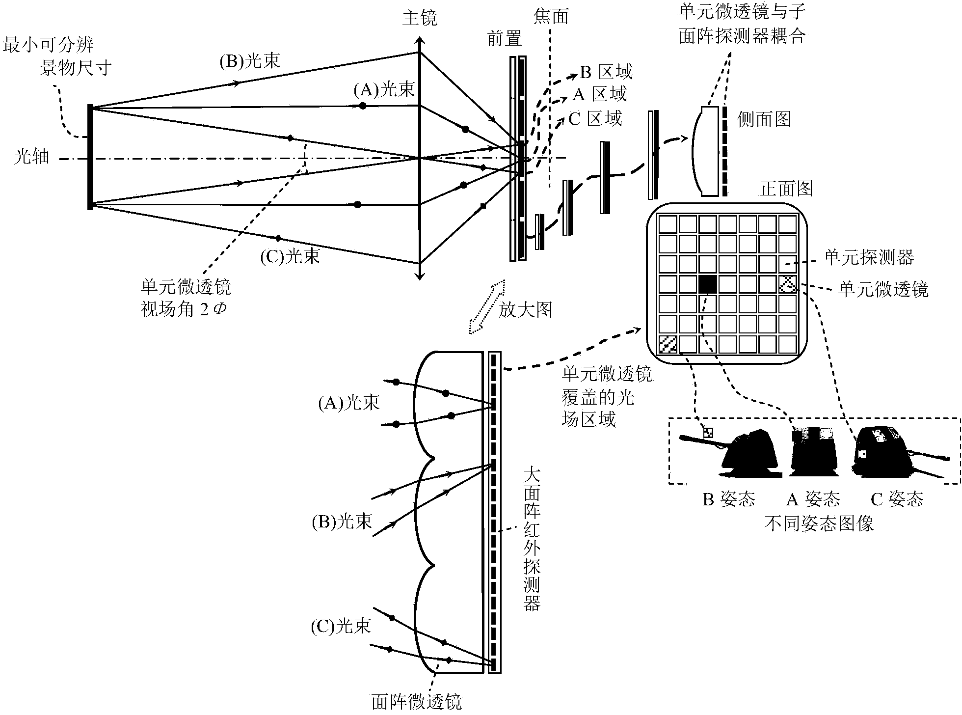
[0024] The infrared radiation characteristics of the material structure show that the digital target image constructed based on the conventional imaging light field is actually a mixture of multiple plane target images with different attitudes. Therefore, by dismantling multiple planar target pose images in the conventional image, it means that based on the spatial distribution characteristics o...


PUM


Abstract

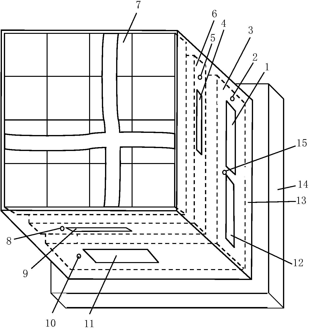
The invention discloses an infrared stereo imaging detection chip which comprises a ceramic shell, a metal support, a heat dissipation board, a drive control and infrared image preprocessing module, an area array non-refrigeration infrared detector and an area array infrared refraction micro lens. The drive control and infrared image preprocessing module, the area array non-refrigeration infrared detector and the area array infrared refraction micro lens are coaxially and sequentially arranged in the ceramic shell. The rear portion of the ceramic shell is arranged on the top of the metal support and the top of the heat dissipation board. The drive control and infrared image preprocessing module is arranged at the joint of the rear portion of the ceramic shell, the metal support and the heat dissipation board. The area array non-refrigeration infrared detector is arranged on the top of the drive control and infrared image preprocessing module, and the area array infrared refraction micro lens is arranged on the top of the area array non-refrigeration infrared detector, wherein the light incident plane of the area array infrared refraction micro lens is exposed through an open hole in the face portion of the ceramic shell. The infrared stereo imaging detection chip has the advantages that stereo image information of a target is detected through single-photosensitive chips in parallel, the infrared stereo imaging detection chip is easily compatible with a conventional infrared optical system, and adaptability of the target and the environment is good.

Description

technical field [0001] The invention belongs to the technical field of infrared imaging detection, and more specifically relates to an infrared stereoscopic imaging detection chip. Background technique [0002] Generally speaking, infrared imaging detection refers to the specific shaping and transformation processing of the received infrared radiation through infrared optical and photoelectric devices, so as to achieve a reasonable distribution of infrared light field on the photosensitive structure of the arrayed detection chip, and then through photoelectric Transforming and constructing an electrical response pattern that adapts to the shape, structure, and radiation (including self-emission, reflection, scattering, or transmission, etc.) characteristics of the target and scene is a process of electronic images. So far, people have continued to develop arrayed infrared detection chip devices, including increasing the array scale of photosensitive chips, reducing the size ...

Claims


Application Information

Patent Timeline
IPC IPC(8): G01J5/10G01J5/02
Inventor 张新宇佟庆康胜武罗俊桑红石谢长生
Owner HUAZHONG UNIV OF SCI & TECH
Learn More