Display method and display module
A display module and display technology, applied in the field of optics and display
- Summary
- Abstract
- Description
- Claims
- Application Information
AI Technical Summary
Problems solved by technology
Method used
Image

Examples
Embodiment 1
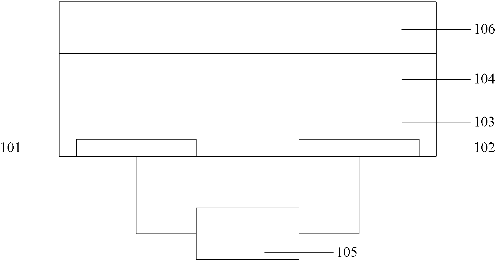
[0069] The display module is a MEMS display module, and the light intensity control unit 104 is a MEMS array.
[0070] In this embodiment, the backlight layer 103 does not include a reflector, the first polarized light source 101 is located at the top of the backlight layer 103 , and the second polarized light source 102 is located at the bottom of the backlight layer 103 . Both the first polarized light source 101 and the second polarized light source 102 are composed of at least one polarized LED, wherein the number of polarized LEDs constituting the first polarized light source 101 is the same as the number of polarized LEDs constituting the second polarized light source 102 .
[0071] In this embodiment, the first polarized light output by the first polarized light source 101 is P-polarized light, and the second polarized light output by the second polarized light source 102 is S-polarized light, and the first polarized light is equal to the second polarized light. pay.
...
Embodiment 2
[0084] The display module is a MEMS display module, and the light intensity control unit 104 is a MEMS array.
[0085] In this embodiment, the backlight layer 103 includes a reflection plate, and the reflection plate is located at the bottom of the backlight layer 103 .
[0086] Both the first polarized light source 101 and the second polarized light source 102 are located on the sidewall of the backlight layer 103 . Both the first polarized light source 101 and the second polarized light source 102 are composed of at least one ordinary LED, wherein the number of ordinary LEDs constituting the first polarized light source 101 is the same as the number of ordinary LEDs constituting the second polarized light source 102 . Polarizers are arranged in front of the common LEDs that make up the first polarized light source 101 and the second polarized light source 102, so that the light output by the first polarized light source 101 and the second polarized light source 102 is polari...
Embodiment 3
[0104] The display module is a MEMS display module, and the light intensity control unit 104 is a MEMS array.
[0105] In this embodiment, the backlight layer 103 includes a reflection plate, and the reflection plate is located at the bottom of the backlight layer 103 .
[0106] Both the first polarized light source 101 and the second polarized light source 102 are located on the sidewall of the backlight layer 103 , wherein the first polarized light source 101 is located on the left sidewall of the backlight layer 103 , and the second polarized light source 102 is located on the right sidewall of the backlight layer 103 .
[0107] Both the first polarized light source 101 and the second polarized light source 102 are composed of at least one ordinary LED, wherein the number of ordinary LEDs constituting the first polarized light source 101 is the same as the number of ordinary LEDs constituting the second polarized light source 102 . Polarizers are arranged in front of the co...
PUM
 Abstract
Description
Claims
Application Information
 - R&D
- Intellectual Property
- Life Sciences
- Materials
- Tech Scout
- Unparalleled Data Quality
- Higher Quality Content
- 60% Fewer Hallucinations
Browse by: Latest US Patents, China's latest patents, Technical Efficacy Thesaurus, Application Domain, Technology Topic, Popular Technical Reports.
© 2025 PatSnap. All rights reserved.Legal|Privacy policy|Modern Slavery Act Transparency Statement|Sitemap|About US| Contact US: help@patsnap.com