Power-factor correction method and circuit and switching power supply

A technology of power factor correction and switching power supply, which is applied in the direction of high-efficiency power electronic conversion, output power conversion device, DC power input conversion to DC power output, etc., and can solve interference with electrical equipment, errors, excessive collection, etc. problem, to achieve the effect of reducing the amount of collection and avoiding errors

Active Publication Date: 2014-01-15
GREE ELECTRIC APPLIANCES INC
View PDF9 Cites 8 Cited by
  • Summary
  • Abstract
  • Description
  • Claims
  • Application Information

AI Technical Summary

Problems solved by technology

[0002] In the actual use of switching power supplies, the load is generally a nonlinear load, which will distort the input current waveform, and the input current is a pulse waveform, which contains a large number of harmonic components, making the power factor very low. The resulting problems...

Method used


Image

  • Power-factor correction method and circuit and switching power supply
  • Power-factor correction method and circuit and switching power supply
  • Power-factor correction method and circuit and switching power supply

Examples


Embodiment Construction

[0038] The following will clearly and completely describe the technical solutions in the embodiments of the present invention with reference to the accompanying drawings in the embodiments of the present invention. Obviously, the described embodiments are only some, not all, embodiments of the present invention. Based on the embodiments of the present invention, all other embodiments obtained by persons of ordinary skill in the art without creative efforts fall within the protection scope of the present invention.

[0039] The embodiment of the invention discloses a power factor correction method, a circuit and a switching power supply, so as to reduce errors during power factor correction.

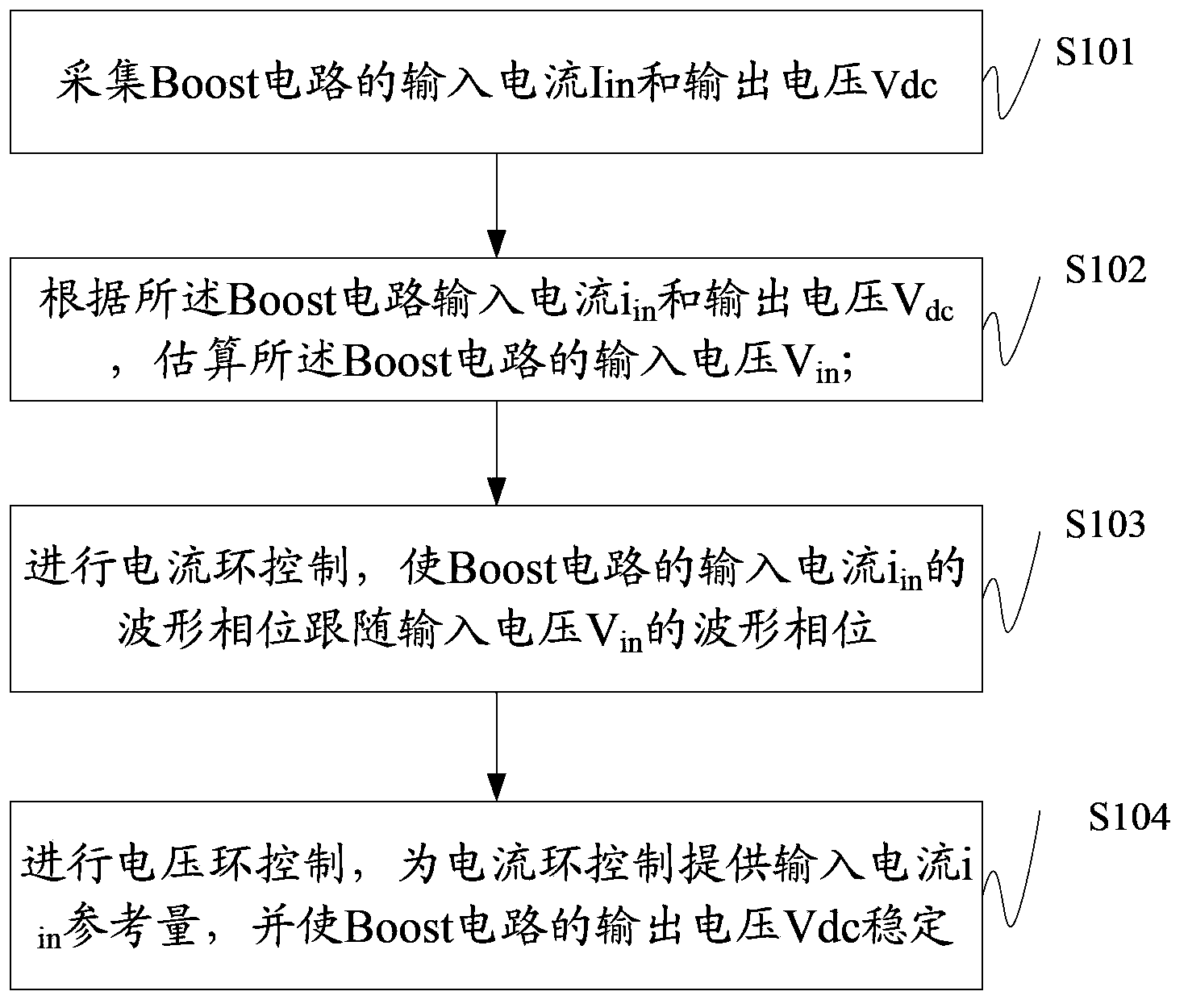
[0040] The power factor correction method disclosed in the embodiment of the present invention is applied to a switching power supply based on a Boost circuit such as figure 1 shown, including steps:

[0041] S101, collecting the input current Iin and the output voltage Vdc of the Boost ...


PUM


Abstract

The invention discloses a power-factor correction method. The power-factor correction method comprises the steps that input currents iin and output voltages Vdc are sampled; input voltages Vin are estimated according to the input currents iin and the output voltages Vdc; electric current loop control is carried out, and the waveform phase of the input currents iin is made to follow the waveform phase of the input voltages Vin; voltage loop control is carried out, the reference quantity of the input currents iin is provided for the electric current loop control, and the output voltages Vdc are made to be stable. According to the power-factor correction method, the input currents and the output voltages of a switching power supply are used as the external variable measured values of a state observer, the input voltages of the switching power supply are obtained by adopting the state observer in an estimation mode, the input voltages do not need to be collected, the collecting quantity is reduced, and errors are avoided. In addition, the input voltages are obtained through the state observer in an estimation mode, and the situation that when the input voltages are collected, power-factor correction accuracy is lowered due to system errors generated by a sampling circuit is avoided.

Description

technical field [0001] The present invention relates to the technical field of power factor correction, and more specifically relates to a power factor correction method, circuit and switching power supply. Background technique [0002] In the actual use of switching power supplies, the load is generally a nonlinear load, which will distort the input current waveform. The input current is a pulse waveform, which contains a large number of harmonic components, making the power factor very low. The resulting problems are: harmonic Wave current pollutes the power grid and interferes with other electrical equipment. Therefore, it is necessary to reduce the harmonic component and correct the power factor. [0003] In the existing power factor correction method, the input current, input voltage and output voltage are collected, and the on-off of the switching tube is controlled according to the collected data, so that the input current and the input voltage are in the same phase,...

Claims


Application Information

Patent Timeline
IPC IPC(8): H02M1/42H02M3/155
CPCY02B70/10
Inventor 孙丰涛胡晰怡曹成赵志刚吕向前
Owner GREE ELECTRIC APPLIANCES INC
Why Eureka
Try Eureka