[0018] The present invention provides an alternative method of converting label stock (a label face web and liner) or linerless label stock (which can then be combined with conventional liner). The label application apparatus (both at he points of applying labels to liners and at the downstream sites where labels are applied to articles of commerce) may use lower weight (thinner) and therefore less expensive liner than can be used with conventional label conversion and application processes.
Label web face (including linerless label webs) may be
cut (the term “
cut,” unless otherwise limited, is defined as including any one of either a complete through cut, microbridged cut as defined herein, or perforated cut which includes all cuts intermediate a microbridged cut and complete through cut having no bridges between the label and the matrix) and then applied to a liner, the adhesive face of the label web face positioned against a release surface of the liner.
Cut label is applied to liner stock (which may include a reusable, temporary liner support) before the cut label stock is applied by a lined label application apparatus or lined label application step. In this manner, the roll of liner(ed) stock or linerless stock material (on a temporary removable liner) may be provided to the ultimate customer of the printshop without that ultimate customer having to be concerned even with the addition of supplemental apparatus such as the component described in U.S. Pat. No. 6,206,071. The apparatus on site with the ultimate customer may not have to be modified in any way from the conventional apparatus used to apply conventional liner label stock. A preferred
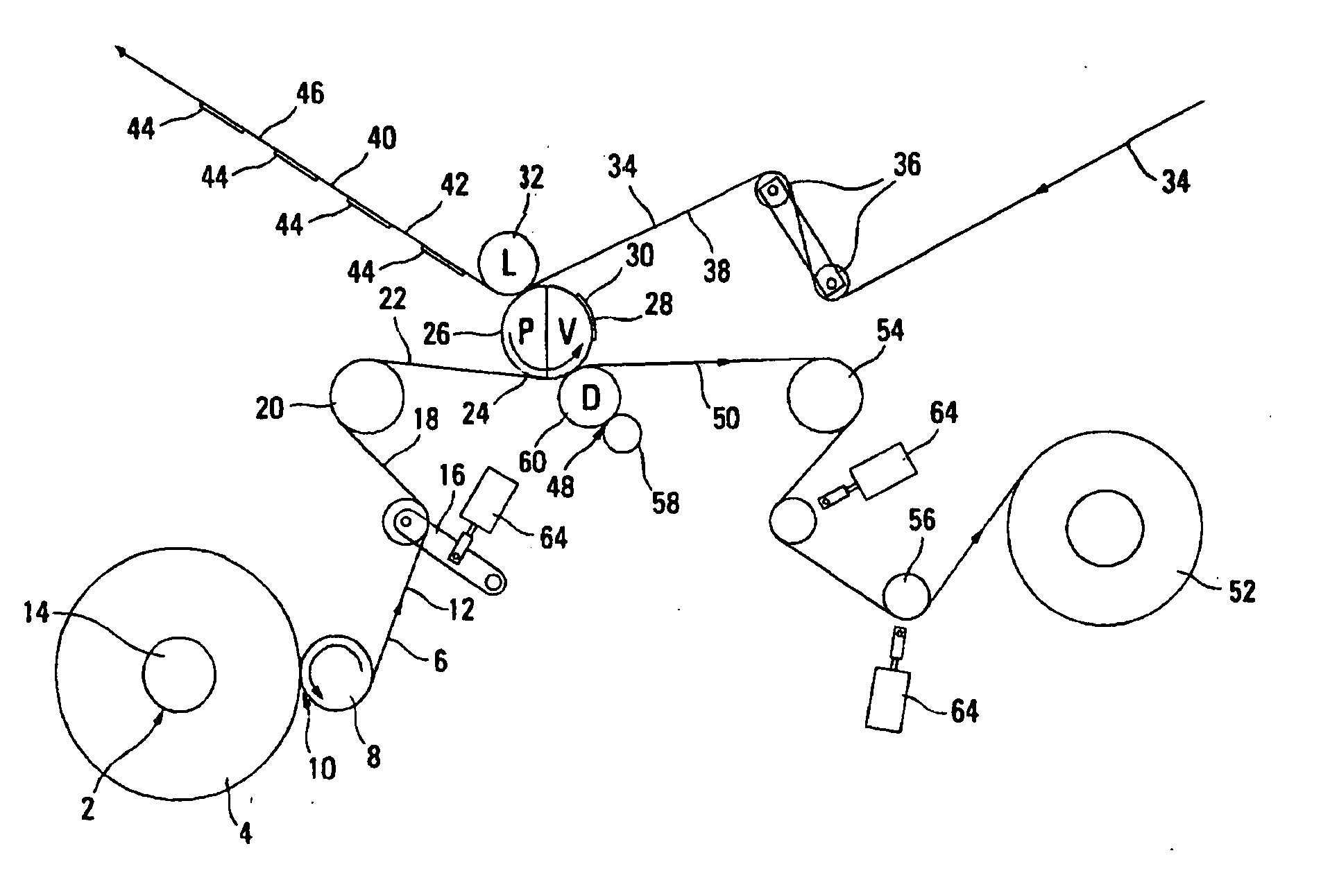
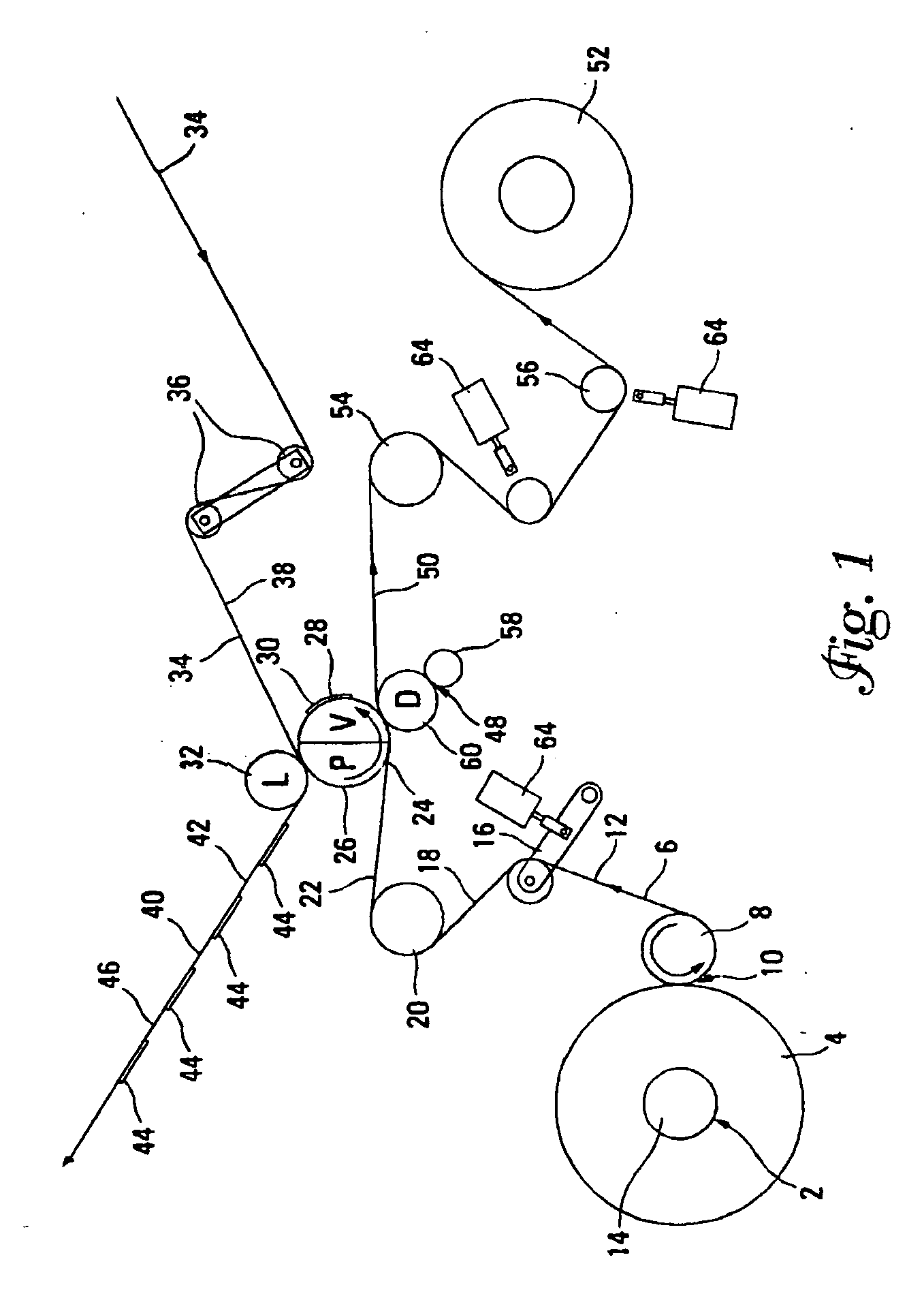
system includes novel apparatus that converts and applies labels to liners and ultimately apparatus that strips labels from liner and applies the labels to articles of commerce.
[0021] An additional process and apparatus for the practice of the present invention comprises a means for reducing the amount of work that has to be performed on a
single line, separating the work onto different lines and even different locations which can reduce cross-
contamination problems of materials used in different segments of the overall process. Particularly the invention allows for printing onto sheets which are cut into materials which form rolls of labels or printing onto the material and directly rolling the printed sheets. Then on a separate line (distinct from the printing line), adhesive (any form of adhesive, including by way of non-limiting examples,
solvent activated adhesive, pressure-sensitive adhesive, repositionable adhesive,
hot melt adhesive, energy activated adhesive, and the like) is applied to the face of the sheet away from the printing (or on the printed face if the label is to be applied printed surface down), preferably, but not necessarily before cutting into the roll width of the printed sheet. It is another surprising aspect of the invention that a thin liner may be provided to the label material after cutting of the label material, enabling the use of thin liner webs in a lined label, without the consequent waste or lack of quality that would be expected from use of thin liners. Because of the generally thin liner layer, the slitting or converting operation of a label on a thin liner might be expected to separate or
wrinkle the
layers. The (preferably printed) label material (sheet, roll or web) with adhesive is cut (e.g., die cut) into the shape desired for the label, the cut label moved through the apparatus with application onto a carrier or liner to form a fully assembled label supply web with a removeable carrier. The matrix is removed from the fully assembled label supply web prior to rewinding into a completed roll. The matrix removal may occur before (or after [preferable] lamination of the label material to the carrier. It is novel according to the present invention to form the roll in the order of printing onto the sheet, applying the adhesive, cutting the labels, and then applying the labels onto the reusable temporary carrier.
[0022] The use of a cooled cutting die (hammer
die cutting implement) is the edge to adhesive or edge to backside or a carrier with adhesive has been found to reduce collection of adhesive within the
system, reduce transfer of adhesive from one component to another, and reduce down time for apparatus necessitated by adhesive removal of label sticking.
[0023] A preferred embodiment of this
die cutting method is to use the
cutting tool to cut a label substrate that has an exposed adhesive surface to the
cutting tool and cooling the
cutting tool down to a temperature that is below the
glass transition temperature of the exposed adhesive. The
glass transition temperature of an adhesive (Tg) is an art recognized characteristic of an adhesive and represents at what temperature it changes from a flowing, soft material to a hard, brittle, glass like material. A unique characteristic of an adhesive is that at or below this Tg temperature, it greatly loses or completely loses its adhesive characteristics. When trying to rotary die cut material where the exposed adhesive necessarily comes in contact with the cutting tool rule, it is desirable to reduce the tackiness between the adhesive and the die, which reduces buildup on the die. In this preferred embodiment the cut or partially cut label material is less likely to stick to the cutting tool. This unique cooling technique eliminates this problem.

