Spar type floating structure

A technology for structures and floating bodies, which is applied to floating buildings, hulls, hydrodynamic characteristics/hydrostatic characteristics, etc., and can solve problems such as difficult to ensure stability, large up and down swings and pitch swings, which are difficult to overcome

Active Publication Date: 2014-01-15
JAPAN MARINE UNITED CORP +2
View PDF8 Cites 9 Cited by
  • Summary
  • Abstract
  • Description
  • Claims
  • Application Information

AI Technical Summary

Problems solved by technology

[0007] However, in the above-mentioned column-type floating body structure, there is a problem that the draft tends to deepen in order to ensure recovery performance, and it is difficult to install it in a shallow sea area.
In addition, compared with the TLP type floating structure, there is a problem that the up and down and pitch (or roll) are larger, and it is difficult to ensure stability.
[0008] In ad...

Method used


Image

  • Spar type floating structure
  • Spar type floating structure
  • Spar type floating structure

Examples


Embodiment Construction

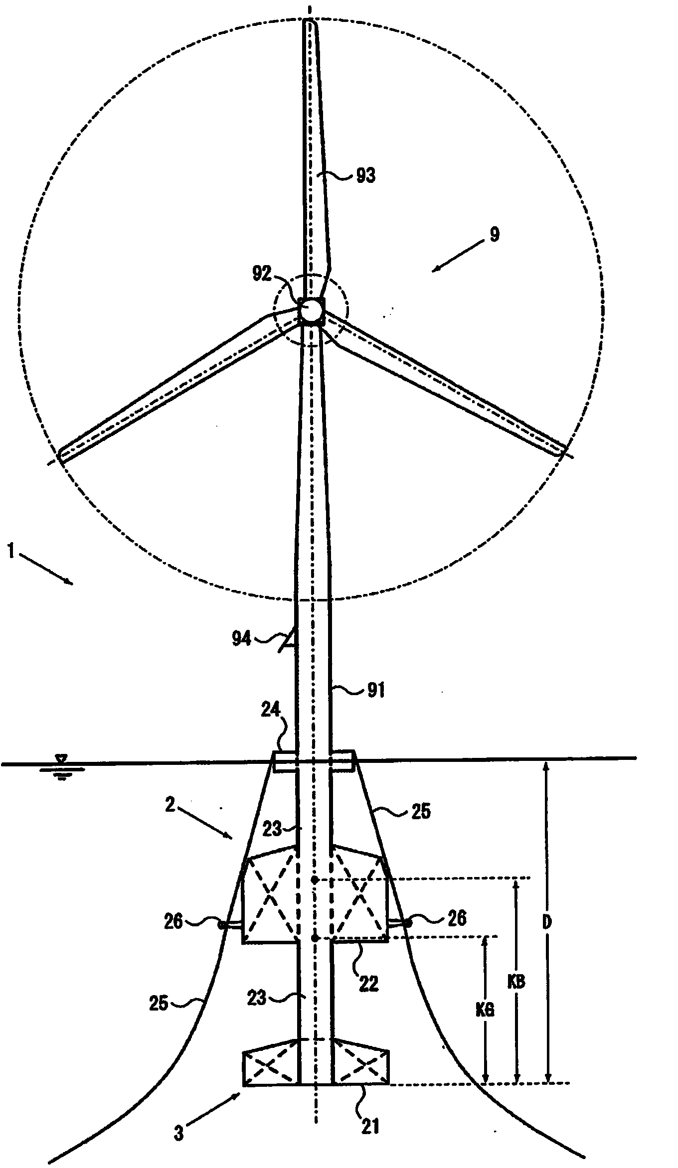
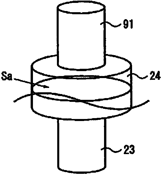
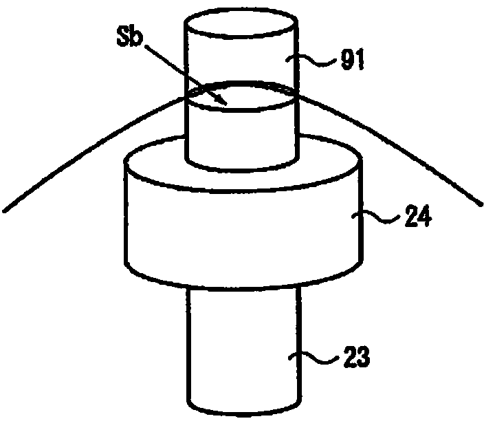
[0041] Next, use figure 1 ~ FIG. 5 demonstrates the columnar floating body structure of embodiment of this invention. here, figure 1 It is an overall configuration diagram of the columnar floating body structure according to the first embodiment of the present invention. Fig. 2 is a diagram for explaining the function of the third expansion part, Figure 2A When representing a normal wave, Figure 2B When high waves are indicated, Figure 2C Represents the wave force characteristic curve. Fig. 3 is a diagram for explaining the function of the second expansion part, Figure 3A Indicates the schematic illustration, Figure 3B Represents the wave force characteristic curve.

[0042] Such as figure 1 As shown, the column-type floating body structure 1 of the first embodiment of the present invention has a floating body part 2 having an elongated shape and a counterweight part 3 disposed on the floating body part 2, and the floating body part 2 is moved by the weight of the...


PUM


Abstract

A spar type floating structure has an elongated floating section (2) and a ballast section (3) which is disposed at the floating section (2), and the spar type floating structure is configured so that the floating section (2) is caused to float while being held in an upright position by the weight of the ballast section (3). The floating section (2) has: a first expanded section (21) disposed at the lower part of the floating section (2) and expanded in the horizontal direction; a second expanded section (22) provided at the intermediate section of the floating section (2) and expanded in the horizontal direction; and a column section (23) for connecting the first expanded section (21) and the second expanded section (22) and extended to the water line. The first expanded section (21) forms the ballast section (3), and the second expanded section (22) forms a floating body which applies a buoyant force to the floating section (2).

Description

technical field [0001] The present invention relates to a column-type floating body structure, and particularly relates to a column-type floating body structure capable of reducing sway while ensuring recovery performance. Background technique [0002] In recent years, offshore wind power generation has attracted attention from the viewpoint of protecting the global environment and effectively utilizing natural energy. As a floating body structure for this kind of offshore wind power generation, various types of floating body structures have been proposed. The center of gravity is always set lower than the center of buoyancy to ensure static stability. The TLP (Tension Leg Platform) type of mooring, the deck and the lower hull are connected by multiple columns to reduce the waterline area (the cross-sectional area of ​​the waterline) and use the phase difference of the wave energy acting on the waterless part to reduce the half of the swing Potential etc. Among these float...

Claims


Application Information

Patent Timeline
IPC IPC(8): B63B35/44B63B21/10B63B35/00B63B39/06B63B43/04
CPCB63B1/048B63B35/44B63B2001/044B63B2035/442B63B2039/067F05B2240/93F03D13/25Y02E10/72Y02E10/727B63B21/10B63B39/06B63B43/04
Inventor 吉本治树粟岛裕治铃木英之
Owner JAPAN MARINE UNITED CORP
Why Eureka
Try Eureka