Filling device for thermal insulation plastering gypsum mortar
A filling device and technology for plastering gypsum, which is applied in the innovative field of gypsum mortar filling, can solve problems such as slurry overflow and affect smooth movement, and achieve the effect of preventing slurry from splashing
- Summary
- Abstract
- Description
- Claims
- Application Information
AI Technical Summary
Problems solved by technology
Method used
Image
Examples
Embodiment 1
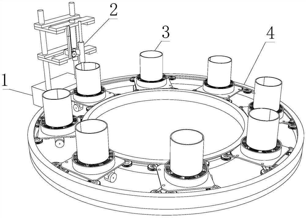
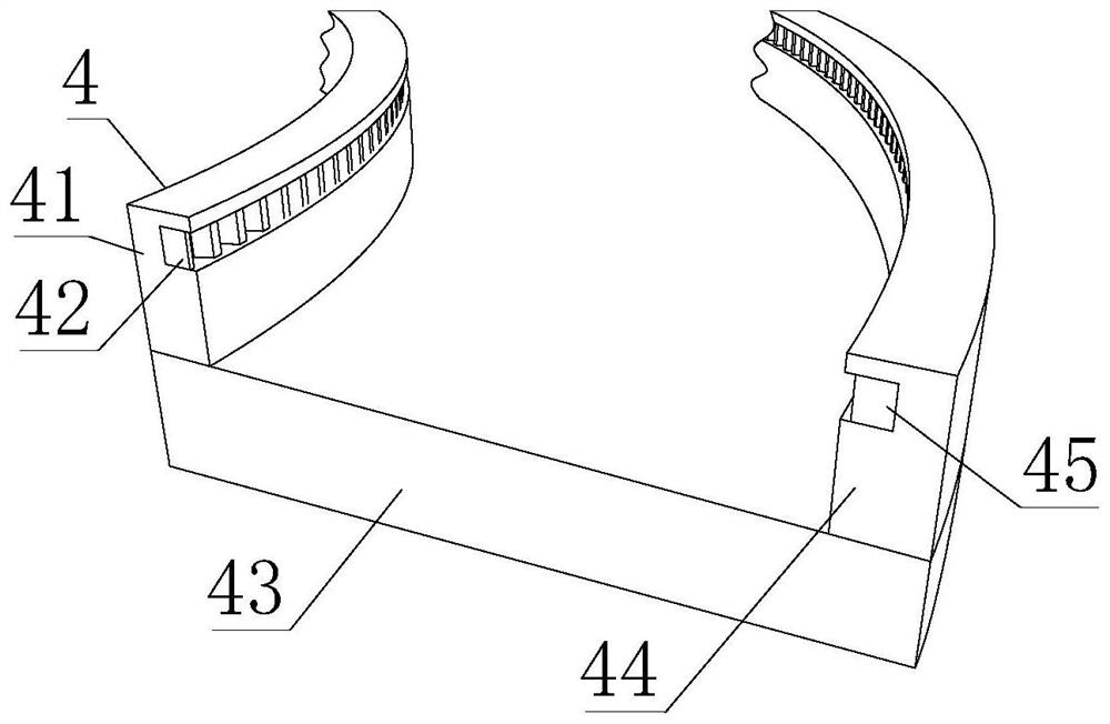
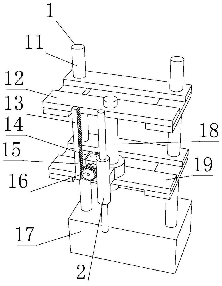
[0033] Such as Figure 1-6 As shown, the present invention provides a filling device for thermal insulation plastering gypsum mortar, including a filling port 2, a mobile splash prevention mechanism 1 is fixedly installed on the outside of the filling port 2, and the mobile splash prevention mechanism 1 includes a rack 13, One side of the rack 13 is movably connected with a driving gear 16, and a single receiving mechanism 3 is provided below the filling port 2. The single receiving mechanism 3 includes a receiving cylinder 31 and a moving plate mechanism 33, and the lower side of the receiving cylinder 31 is overlapped. Anti-sway mechanism 32 is arranged, and anti-sway mechanism 32 comprises radian sector piece 322, and movable disk mechanism 33 comprises V-shaped bar 339, and the outside of movable disk mechanism 33 is connected with fixed disk mechanism 4, and fixed disk mechanism 4 comprises internal fixed disk 41.
[0034] In this embodiment, by setting the mobile anti-sp...
Embodiment 2
[0036] Such as Figure 1-6As shown, on the basis of Embodiment 1, the present invention provides a technical solution: preferably, the upper rear side upper part of the rack 13 is fixedly connected with the upper support frame 12, and the rear side lower part of the rack 13 is fixedly connected with the lower support frame 19. The middle part of the lower support frame 19 is fixedly connected with a movable column 18, and the outer surface of the movable column 18 is slidably connected with a movable column cover 14, and the inside of the upper support frame 12 is fixedly installed with a fixed column 11, and the lower side of the fixed column 11 is fixedly connected There is a base 17, the outer surface of the fixed column 11 is fixedly installed with the inside of the lower support frame 19, the outer surface of the movable column 18 is fixedly connected with the inside of the upper support frame 12, and the inside of the movable column cover 14 is fixedly installed with a se...
Embodiment 3
[0039] Such as Figure 1-6 As shown, on the basis of Embodiment 1, the present invention provides a technical solution: preferably, the lower side of the V-shaped bar 339 is rotatably connected with a steering gear 338, and the upper side of the V-shaped bar 339 is rotatably connected with a moving plate 331, The lower left part of the moving plate 331 is rotatably connected with a secondary gear 332, the outer side of the secondary gear 332 is movably connected with a worm 333, and the outer surface of the worm 333 is rotatably connected with a shaft sleeve 334, and the upper side of the shaft sleeve 334 is connected with the moving plate 331. The lower side of the moving plate 331 is fixedly connected with the connecting block 336, the lower side of the connecting block 336 is fixedly connected with the second servo motor 335, and the right side of the second servo motor 335 is fixedly equipped with a primary gear 337, a primary gear The upper side of 337 is movably connecte...
PUM
 Abstract
Description
Claims
Application Information
 - R&D
- Intellectual Property
- Life Sciences
- Materials
- Tech Scout
- Unparalleled Data Quality
- Higher Quality Content
- 60% Fewer Hallucinations
Browse by: Latest US Patents, China's latest patents, Technical Efficacy Thesaurus, Application Domain, Technology Topic, Popular Technical Reports.
© 2025 PatSnap. All rights reserved.Legal|Privacy policy|Modern Slavery Act Transparency Statement|Sitemap|About US| Contact US: help@patsnap.com


