
Reciprocating water pumping vat

A reciprocating and water cylinder technology, which is applied in variable capacity pump components, liquid variable capacity machines, components of pumping devices for elastic fluids, etc., can solve the problems of single pumping, economic loss of production enterprises, High manufacturing cost and other issues, to avoid cooling water splashing, easy to use and move, and improve production safety

Pending Publication Date: 2019-06-07
重庆特博智能装备有限公司
View PDF11 Cites 0 Cited by
  • Summary
  • Abstract
  • Description
  • Claims
  • Application Information

AI Technical Summary

Problems solved by technology

However, in the process of replacing the electrode cap, too much residual cooling water in the welding torch pipeline will cause splashing, which will cause many safety problems: such as electric shock hazard, slip hazard; a large amount of cooling water will also corrode and damage equipment and products , causing severe economic losses
[0003] At present, the existing water pumping tanks can basically only pump water once, and cannot realize the continuous pumping function, so the remaining water in the pipeline cannot be completely drained, so it will also cause corresponding safety problems and cause serious damage to the production enterprise. Economic loss, while the overall structure is complex and the manufacturing cost is high

Method used


Image

  • Reciprocating water pumping vat
  • Reciprocating water pumping vat
  • Reciprocating water pumping vat

Examples


Embodiment Construction

[0024] The present invention will be further described in detail below in conjunction with test examples and specific embodiments. However, it should not be understood that the scope of the above subject matter of the present invention is limited to the following embodiments, and all technologies realized based on the content of the present invention belong to the scope of the present invention.

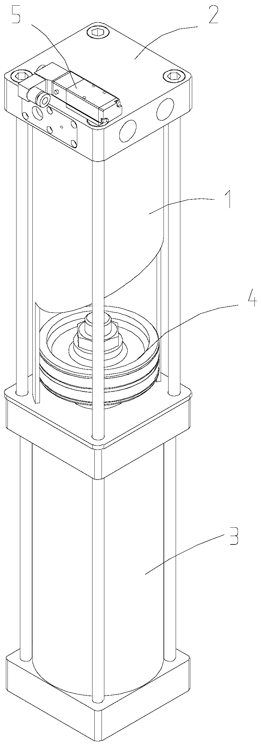
[0025] as attached figure 1 - attached Figure 4 The shown reciprocating pumping cylinder includes a water cylinder 1, the upper end of the water cylinder 1 is connected with an end cover assembly 2, and its lower end is connected with a cylinder 3, and the movable end of the cylinder 3 is fixed to the piston 4 located in the inner cavity of the water cylinder 1. Connection, the end cover assembly 2 is connected with a solenoid valve 5 .

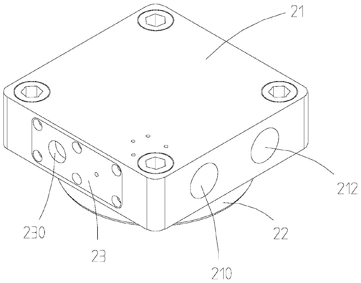
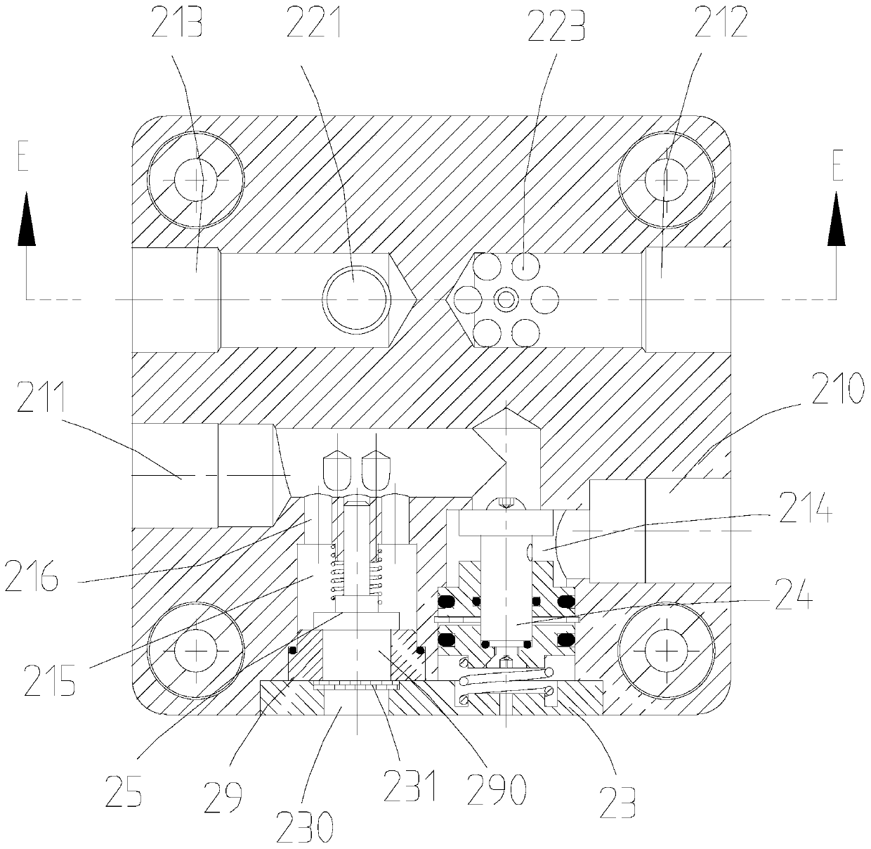
[0026] Please refer to figure 2 . image 3 and Figure 4 The above-mentioned end cover assembly 2 includes an end cover body, which includes...


PUM


Abstract

The invention discloses a reciprocating water pumping vat. The reciprocating water pumping vat comprises a water vat; the upper end of the water vat is connected with an end cover module, and the lower end is connected with a cylinder; the end cover module is connected with an electromagnetic valve; the end cover module comprises an end cover main body, and is provided with a first water inlet hole, a first water outlet hole, a second water inlet hole, a second water outlet hole and a stop valve mounting hole; a stop valve is mounted in the stop valve mounting hole; the end cover main body isprovided with a water inlet valve element mounting hole, a water outlet valve element mounting hole and a water inlet and outlet valve base; a water inlet valve element is mounted in the water inlet valve element mounting hole; a water outlet valve element is mounted in the water outlet valve element mounting hole; first communicating holes are distributed on the water inlet and outlet valve baseand located around the water inlet valve element; the water inlet valve element mounting hole communicates with an inner cavity of the water vat through the first communicating holes; a first valve base via hole is formed in the water inlet and outlet valve base and corresponds to the water outlet valve element; second communicating holes are distributed on the end cover main body and located around the water outlet valve element; and the water outlet valve element mounting hole communicates with the second water outlet hole through the second communicating holes.

Description

technical field [0001] The invention relates to the technical field of welding production, in particular to a reciprocating water pumping cylinder. Background technique [0002] The competition in the automobile market is becoming more and more fierce. To be in an invincible position in the automobile industry, it is necessary to improve production efficiency in automobile production and reduce the manufacturing cost of automobiles, and welding plays a vital role in this link. Especially in the production mainly based on resistance spot welding, in order to ensure the production quality, the electrode cap often needs to be ground and replaced. However, in the process of replacing the electrode cap, too much residual cooling water in the welding torch pipeline will cause splashing, which will cause many safety problems: such as electric shock hazard, slip hazard; a large amount of cooling water will also corrode and damage equipment and products , causing serious economic lo...

Claims


Application Information

Patent Timeline
Patent Type & Authority Applications(China)
IPC IPC(8): F04B9/12F04B53/10F04B53/16
Inventor 廖波
Owner 重庆特博智能装备有限公司
Learn More