Exhaust gas purification system for working machine

An exhaust gas purification system and operating machine technology, applied in exhaust gas treatment, electrical control, mechanical equipment, etc., can solve problems such as DPF damage, neglect of the importance of manual regeneration, and rise in filter internal temperature to achieve the effect of preventing damage

Inactive Publication Date: 2014-01-15
NIHON KENKI CO LTD
View PDF7 Cites 12 Cited by
  • Summary
  • Abstract
  • Description
  • Claims
  • Application Information

AI Technical Summary

Problems solved by technology

Operators may be so focused on the job that they may not notice warnings urging manual regeneration
In addition, there is also the possibility of over-prioritizing the execution of the job and ignoring the importance of manual regeneration
If manual regeneration is not performed even though a warning to urge manual regeneration is issued, the following problems may occur: PM continues to accumulate, and the internal temperature of the filter increases abnormally due to the combustion of a large amount of trapped PM, which may cause damage to the DPF.

Method used


Image

  • Exhaust gas purification system for working machine
  • Exhaust gas purification system for working machine
  • Exhaust gas purification system for working machine

Examples


no. 1 Embodiment approach

[0033] Hereinafter, a first embodiment of the present invention will be described using the drawings.

[0034] ~Structure~

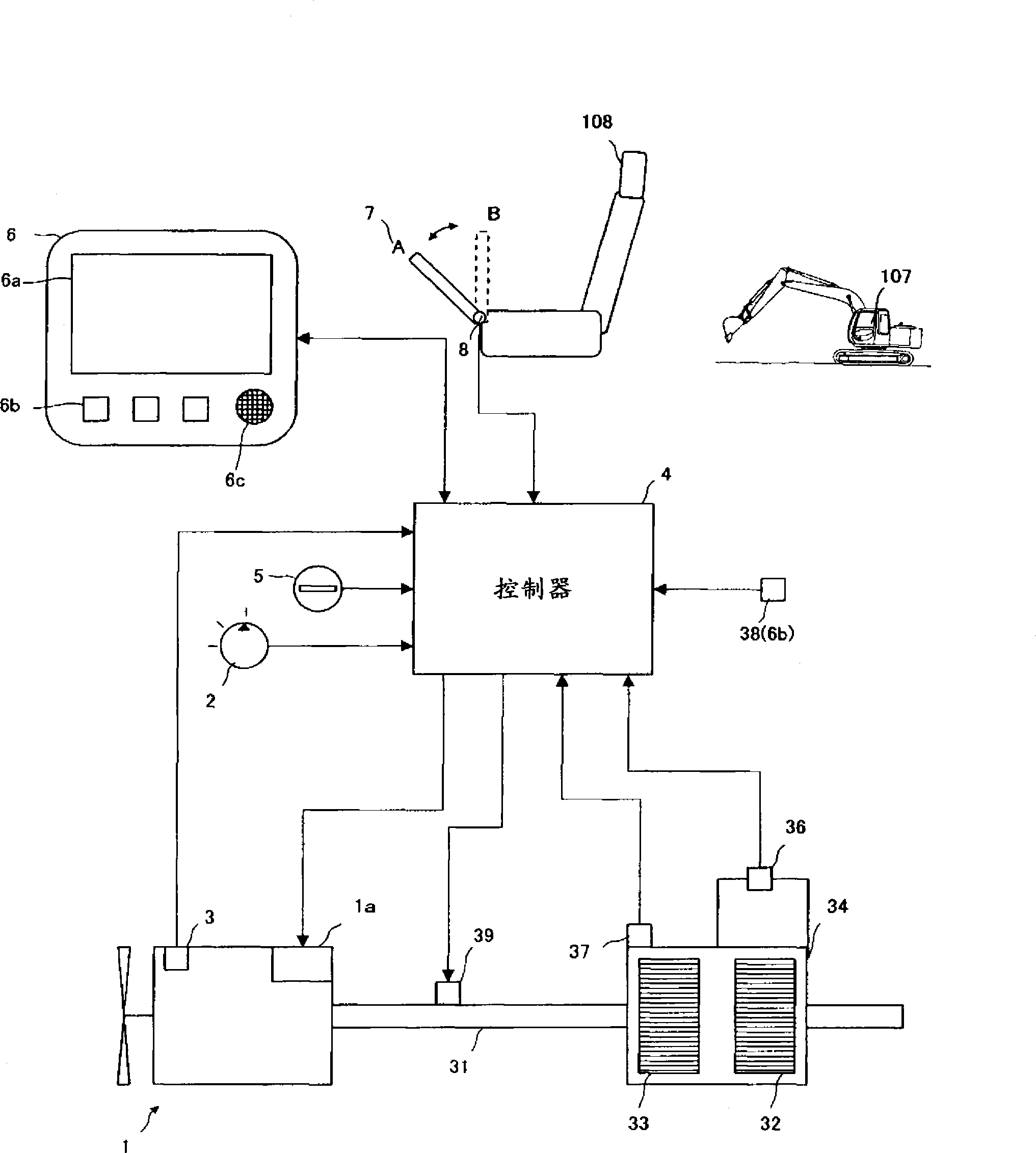
[0035] figure 1It is a figure which shows the whole structure of the exhaust gas purification system of the working machine which concerns on this Embodiment of this invention.

[0036] A work machine (for example, a hydraulic excavator) is equipped with a diesel engine 1 having an electronic governor 1 a as an electronic fuel injection control device. The target rotational speed of the engine 1 is commanded through the engine control dial 2 , and the actual rotational speed of the engine 1 is detected by the rotational speed detection device 3 . The command signal of the engine control dial 2 and the detection signal of the speed detection device 3 are input to the controller 4, and the controller 4 controls the electronic governor 1a according to the command signal (target speed) and the detection signal (actual speed), thereby controlling the engine...

no. 2 Embodiment approach

[0117] ~Technical Issues~

[0118] In the control of the first embodiment, the operation of the exhaust gas purification system when returning from the standby state to the working state will be described. During standby, PM accumulation may worsen than during operation. Therefore, when it is determined that the hydraulic excavator is in the working state and the set times t1, t2, and t3 corresponding to the working state are reset, the set time t1 corresponding to the working state is determined based on the elapsed time measured during standby. , t2, t3, in fact, the change of the warning sound is delayed.

[0119] use Figure 6 Further details. Figure 6 It is a conceptual diagram explaining the outline of technical problems caused by the difference in setting time between the standby state and the working state. The horizontal axis is time, and the vertical axis is accumulation amount. Let the PM accumulation amount for which the warning sound should be changed be the...


PUM


Abstract

The present invention provides an exhaust gas purification system for working machine, in which a warning for urging regeneration is more reliably given to an operator, and proper manual regeneration is performed, thereby enabling DPF damage to be prevented. When a PM sedimentation amount is larger than a predetermined value, a warning for urging manual regeneration is displayed on a display screen (6a). When manual regeneration is not performed even with warning display, and time (t1) elapses from display of regeneration warning, a first warning tone is output from a speaker (6c). When the operator recognizes the first warning tone, and operates a regeneration switch (38), regeneration control starts. When the operator can not recognize the first warning tone, and time (t2) elapses from the display of the regeneration warning, a second warning tone (warning tone stronger than the first warning tone) is output from the speaker (6c) in place of the first warning tone. When the operator recognizes the second warning tone, and operates the regeneration switch (38), the regeneration control starts.

Description

technical field [0001] The present invention relates to an exhaust gas purification system for working machines, and more particularly to a system for purifying exhaust gas by trapping particulate matter contained in exhaust gas through a filter, and giving appropriate warnings to urge combustion to remove the particulate matter trapped on the filter. Exhaust gas purification system that regenerates the filter with substances. Background technique [0002] Work machines such as hydraulic excavators are equipped with a diesel engine as their driving source, but the amount of particulate matter (PM: Particulate Matter, hereinafter referred to as PM) discharged from the diesel engine and the NO x , CO, HC, etc. are strengthened year by year. In response to such restrictions, there is known an exhaust gas purification system that traps PM with a filter called a diesel particulate filter (DPF: Diesel Particulate Filter) to reduce the amount of PM discharged to the outside. In t...

Claims


Application Information

Patent Timeline
Patent Type & Authority Applications(China)
IPC IPC(8): F01N3/023B01D53/94E02F9/00B01D46/42
CPCE02F9/2095E02F9/2282E02F9/2285E02F9/2296E02F9/267F01N3/035F01N11/00F01N2550/04F01N2590/08F02D41/029F01N3/0253E02F9/2066F02D2041/228F02D2200/0812F02D2200/604F01N3/023Y02T10/40
Inventor 柴森一浩渡边丰束田英信中村惠一郎木村彰后藤勇树藤枝晃太
Owner NIHON KENKI CO LTD
Why Eureka
Try Eureka