Dust separation and collection device

A collection device and dust separation technology, which is applied in solid separation, separation of solids from solids by air flow, and plastic recycling. , Reduce the effect of secondary adhesion

Active Publication Date: 2014-01-22
宁波斯曼尔电器有限公司
View PDF8 Cites 23 Cited by
  • Summary
  • Abstract
  • Description
  • Claims
  • Application Information

AI Technical Summary

Problems solved by technology

The disadvantage of this invention is that the plastic particles are still easy to mix with the dust, and the separated dust is still easy to flow back and rebound with the air before being recycled, and is mixed into the plastic particle pile again, resulting in insufficient separation

Method used


Image

  • Dust separation and collection device
  • Dust separation and collection device
  • Dust separation and collection device

Examples


Embodiment 1

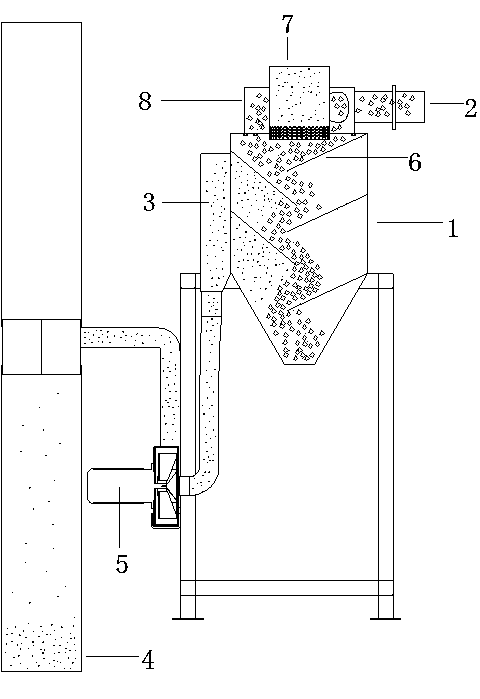
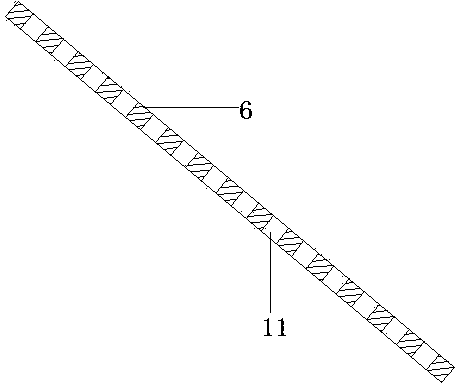
[0025] Embodiment 1: as figure 1 A frequency conversion separation device for plastic dust is shown, which includes a dust removal main cylinder 1 and a feed port 2. The dust removal main cylinder 1 is connected to a dust collection bag 4 through an air guide pipe 3, and the air guide pipe 3 is A wind-guiding and dust-absorbing fan 5 is provided, a plurality of material-guiding sloping plates 6 are arranged inside the dust removal main cylinder 1, and a discharge port is provided at the lower end of the dust removal main cylinder 1 . The main dust removal cylinder 1 is provided with a cyclone cylinder 7, and the side wall of the cyclone cylinder 7 is provided with a dust suction mesh. The direction is from bottom to top, the cyclone 7 is located at the upper end of the dust removal main cylinder 1, and the cyclone 7 is provided with a pre-dust removal tube 8, and the pre-dust removal tube 8 is connected to the feed port 2. The sloping material guide plates 6 are located on bo...

Embodiment 2

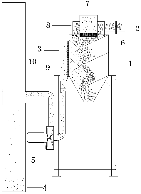
[0027] Embodiment 2: as figure 2 , image 3 The present embodiment shown, its structure and implementation mode are basically the same as embodiment 1, the difference is that a wind collecting plate 9 is provided on the material guide sloping plate 6 close to the air guide pipe 3 side, and the wind collecting plate 9 The end away from the air guide pipe 3 is connected to the lower surface of the sloping material guide plate 6, and an air gathering port is formed between the wind gathering plate 9 and the sloping material guide plate 6 below. The existence of the air-gathering port can accelerate the speed and strength of the suction airflow, and after the airflow accelerates, some plastic particles will deviate accordingly, hit the wind-gathering plate 9 and be rebounded downwards, which increases the number of collisions and ensures the adsorption. The dust is shaken away from the plastic particles to improve the separation effect. The lower end of the half cylinder part o...


PUM


Abstract

The invention discloses a dust separation and collection device which is good in separation effect, can sufficiently and thoroughly separate and recycle dust and solves the deficiencies that partial plastic is separated along with the dust, and the dust is easy to rebound, mix and adhere again in a separation process of a plastic dust separation device in the prior art. A plastic dust frequency-conversion separation device comprises a main dust removing cylinder and a feeding hole, wherein the main dust removing cylinder is connected with a dust collection bag through an air guiding pipe, an air guiding and dust collection fan is arranged on the air guiding pipe, a plurality of material-guiding inclined plates are arranged in the main dust removing cylinder, and a discharging hole is formed in the lower end of the main dust removing cylinder; a cyclone cylinder is arranged on the main dust removing cylinder, dust collection meshes are formed in the side wall of the cyclone cylinder, and a pre-dedusting cylinder is arranged outside the cyclone cylinder and is connected with the feeding hole. The dust separation and collection device is suitable for applicative occasions of existing plastic dust separation devices and has the characteristics of capability of complete scattering and separation of plastic particles, good dust removing effect, high separation efficiency and the like.

Description

[0001] technical field [0002] The invention belongs to the field of dust separation, in particular to a dust separation and collection device. [0003] Background technique [0004] When recycling plastics, it is necessary to use a shredder to crush plastic parts into plastic particles. After crushing, there is a large amount of dust in the plastic particles, which need to be separated and recycled before the plastic particles can enter the next processing link. At present, in the process of separating plastic particles and dust, centrifugal separators are mainly used to blow the crushed plastic particles centrifugally. Since the dust is relatively light, it will be thrown to the side wall of the separator first to achieve separation. However, due to the low quality of the plastic particles in this separation method, part of the plastic particles will be thrown to the side wall of the separator along with the dust during separation. Moreover, the dust is easy to mix in ag...

Claims


Application Information

Patent Timeline
Patent Type & Authority Applications(China)
IPC IPC(8): B29B17/02B07B9/02B07B11/02
CPCY02W30/62
Inventor 卢华乔刘自强
Owner 宁波斯曼尔电器有限公司
Why Eureka
Try Eureka