Injection mold of staggered spiral line type hollow propelling pipe

A technology of injection molds and propulsion tubes, which is applied to household appliances, other household appliances, household components, etc., can solve the problems of complex structure and cumbersome demoulding process, and achieve the effect of uniform product quality, stable performance, and rapid injection molding process

Inactive Publication Date: 2014-01-22
HENAN POLYTECHNIC INST
View PDF5 Cites 5 Cited by
  • Summary
  • Abstract
  • Description
  • Claims
  • Application Information

AI Technical Summary

Problems solved by technology

The structure of the above-mentioned invention adopts a slider and a spiral core structure. The spiral core relies on the rotation of the split-type oblique bearing to achieve the ejection of the plastic product by the

Method used


Image

  • Injection mold of staggered spiral line type hollow propelling pipe
  • Injection mold of staggered spiral line type hollow propelling pipe
  • Injection mold of staggered spiral line type hollow propelling pipe

Examples


specific Embodiment 1

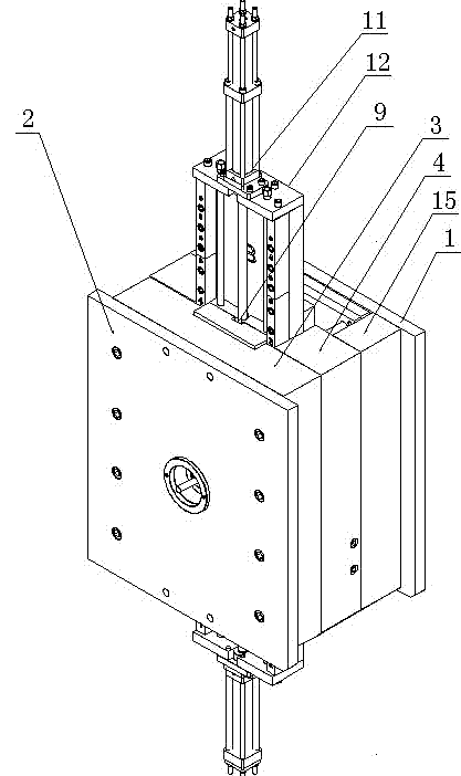
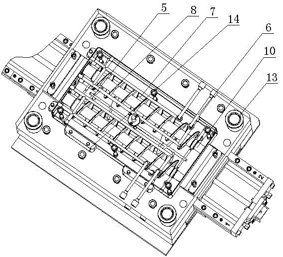
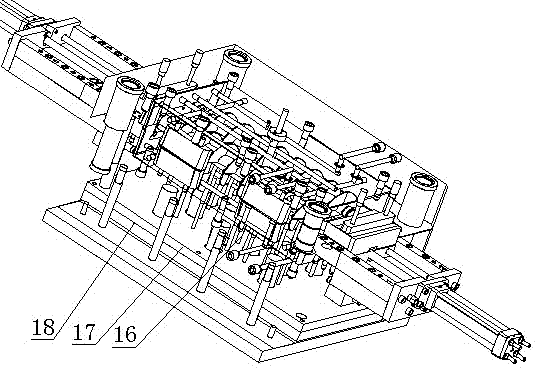
[0042] like figure 1 , figure 2 and image 3 As shown, an injection mold for a dislocated helical hollow propulsion tube includes a mold bottom plate 1, a pressure plate 2, a moving template 3 with two halves combined, a fixed template 4, a pouring system 5, a cooling system 6 and a core-pulling mechanism 9, The movable template 3 and the fixed template 4 are respectively provided with insert components 7, and the cavity surface formed by the insert components 7 is processed with a half-helix structure 8, and the two half-helix structures 8 are staggered and combined, so that A core 10 with a circular section is inserted in the middle of the cavity surface, an axial groove is arranged on one side of the core 10, the core pulling mechanism 9 is connected to a hydraulic cylinder 11, and slider structures 12 are fixed on both sides of the mold. The hydraulic cylinder 11 is arranged on the slider structure 12 through the cylinder fixing block.

[0043] The slider structure 12 ...

specific Embodiment 2

[0053] The difference from Embodiment 1 is that: the cooling water channels include two groups uniformly distributed outside the cavity.

specific Embodiment 3

[0054] The difference from the first embodiment is that the number of gates is four evenly distributed.


PUM


Abstract

The invention discloses an injection mold of a staggered spiral line type hollow propelling pipe. The injection mold comprises a mold bottom plate, a pressing plate, a half movable template, a half fixed template, a pouring system, a cooling system and a core pulling structure, wherein the half movable template and the half fixed template are put together, the inside of the movable template and the inside of the fixed template are respectively provided with an insert component, a semi-spiral structure is machined on a mold cavity face formed by each insert component, the two semi-spiral structures are staggered and put together oppositely, a cylindrical mold core with one axial groove in one side is inserted into the middles of the mold cavity faces, the core pulling structure is connected with a hydraulic cylinder, the two sides of the mold are respectively and fixedly provided with a sliding block structure, and oil cylinder fixing blocks used for the hydraulic cylinder are arranged on the sliding block structures. According to the injection mold, the mold cavities can be in two halves and are put together oppositely, the semi-spiral structures are staggered and put together oppositely, a transition plane is formed at the joint portion of the spiral faces, the mold finished product rate is substantially improved, product performance is excellent, the long cylindrical mold core can provide power through the core pulling structure connected with the hydraulic cylinder, the hydraulic cylinder slides in a limited mode, the guide accuracy is high, the injection mold is of a structure with two cavities, and the production rate is high.

Description

technical field [0001] The invention belongs to the technical field of molds for processing spiral products, and in particular relates to an injection mold for a dislocation helical hollow propulsion tube. Background technique [0002] At present, the spiral propulsion tube is widely used in industry, mainly used in water supply engineering, petrochemical industry, chemical industry, electric power industry, agricultural irrigation, especially in water supply, drainage, sewage treatment engineering, mud transportation, material particle transfer, marine piling tube and other fields. It is mainly to use its structural characteristics to realize spiral propulsion or export, and push the material from the collecting hopper to the next equipment. Commonly used steel structure welding parts and plastic injection molding parts. For example, the patent application number: 201320001560.X discloses a substrate removal device, which includes a slope collection mechanism and a scr...

Claims


Application Information

Patent Timeline
IPC IPC(8): B29C45/36B29C45/27B29C45/33B29C45/73
CPCB29C33/76B29C45/26B29C45/2708B29C45/32B29C45/33B29C45/332B29C45/36B29C45/4005B29C2045/2712B29C2045/363B29L2031/7732
Inventor 余东满李晓静高志华王笛户燕会李成思方雅孙育竹
Owner HENAN POLYTECHNIC INST
Why Eureka
Try Eureka