Independent-tool-setting type 3D multi-functional numerical control carving machine

A CNC engraving machine, multi-functional technology, applied in the direction of engraving, processing models, decorative arts, etc., can solve the problem of lack of multi-functional engraving machines, and achieve the effect of improving engraving accuracy, high work efficiency, and improving equipment adaptability

Inactive Publication Date: 2014-01-22
安庆市宏大涛业精啄数控科技有限公司
View PDF9 Cites 6 Cited by
  • Summary
  • Abstract
  • Description
  • Claims
  • Application Information

AI Technical Summary

Problems solved by technology

[0006] To sum up, the prior art has plane engraving machines, cylindrical engraving machines and other equipment, but there is a lack of multifunctional engraving machines that can simultaneously perform plane engraving, cylinder outer surface engraving, and three-dimensional 3D engraving. There is still room for improvement in drive (gantry) and Y drive

Method used


Image

  • Independent-tool-setting type 3D multi-functional numerical control carving machine
  • Independent-tool-setting type 3D multi-functional numerical control carving machine
  • Independent-tool-setting type 3D multi-functional numerical control carving machine

Examples


Embodiment 1

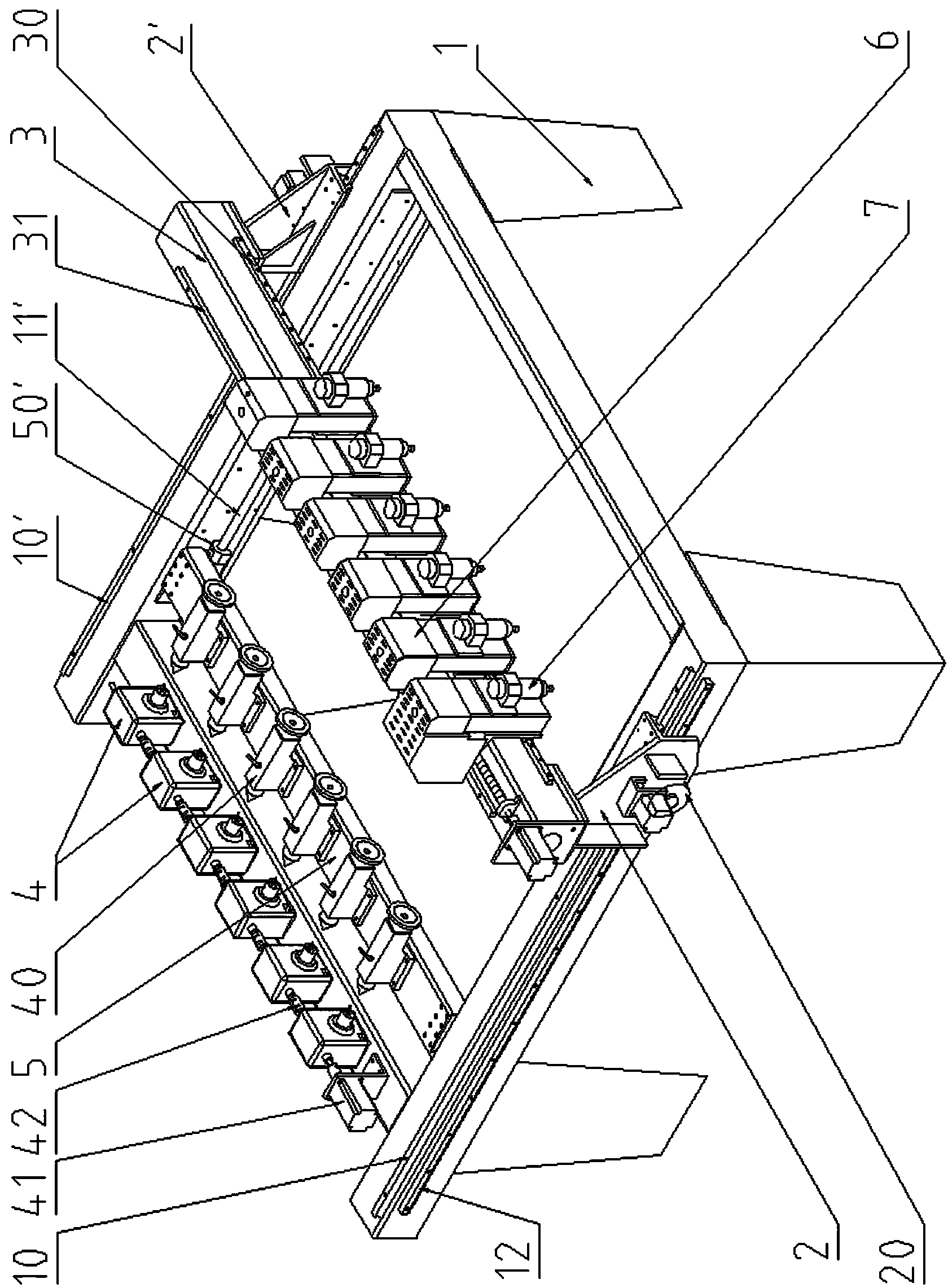
[0043] Depend on Figure 1 to Figure 6 It can be seen that, in this embodiment, the Y-direction drive device adopts a rack drive mode, and both sides are synchronously driven.

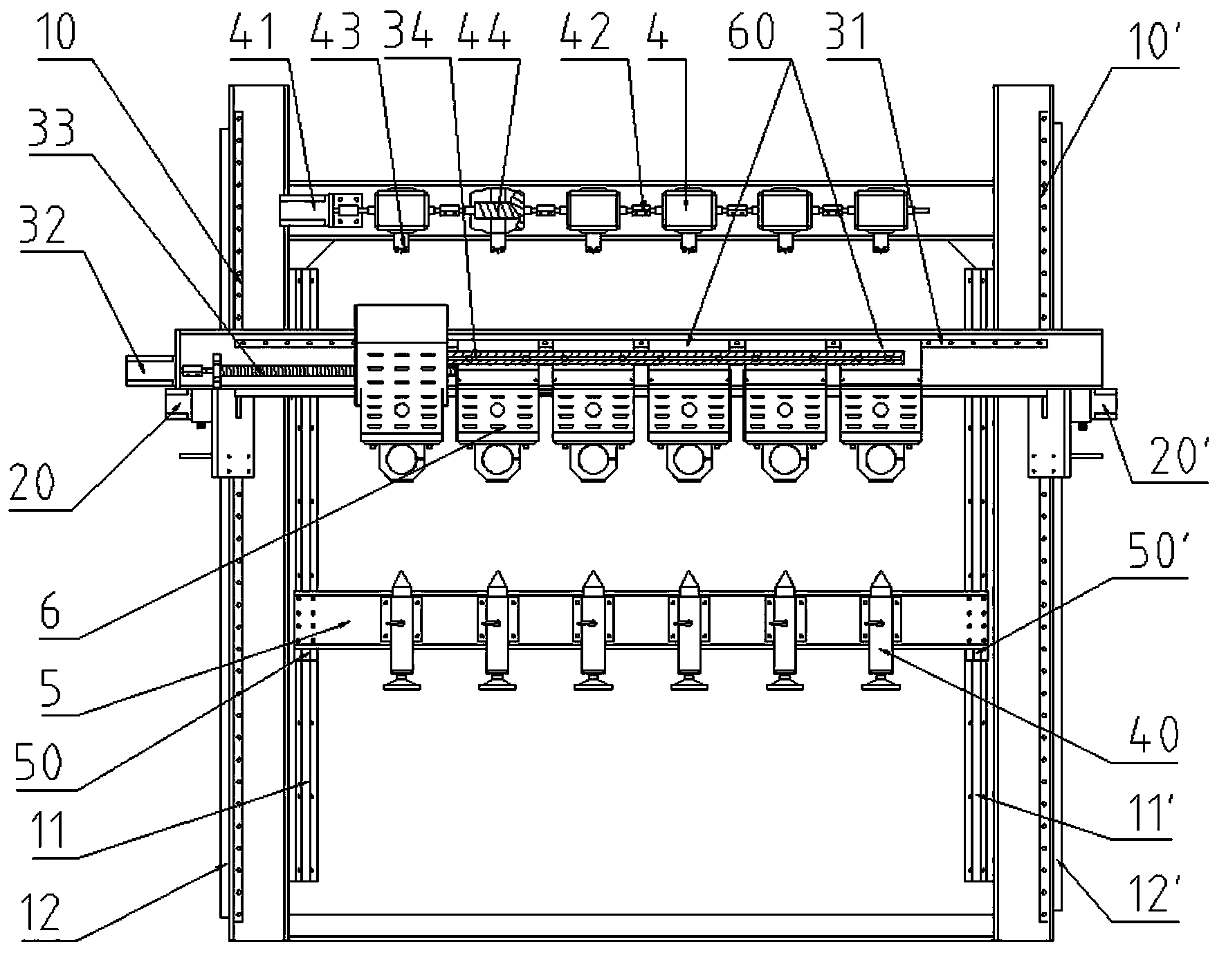
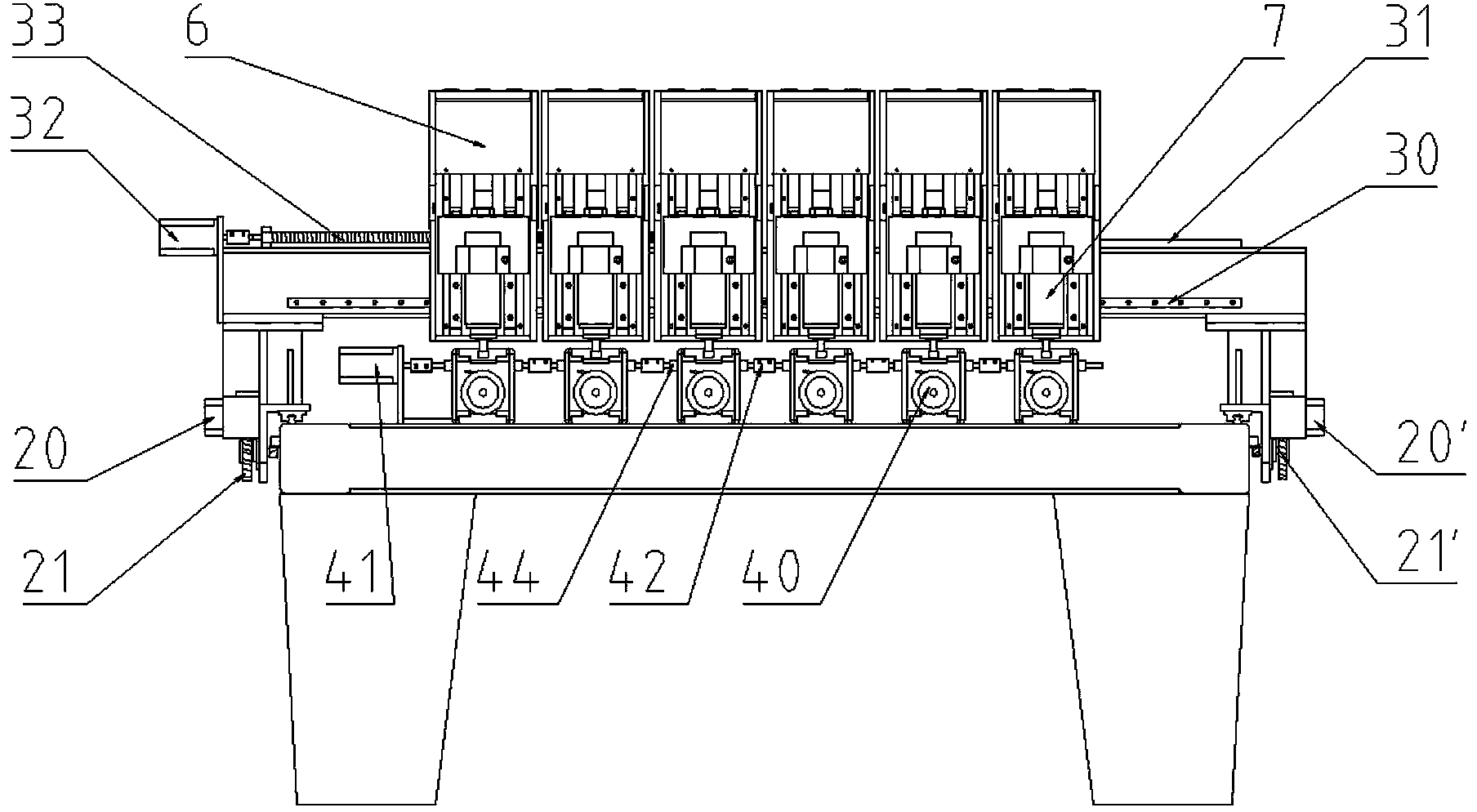
[0044] In the independent knife-setting type 3D three-dimensional multifunctional CNC engraving machine of this embodiment, its Y-direction driving device includes left and right Y-direction racks 12, 12' arranged on the bed body 1, and also includes left and right columns 2, 12', The left and right Y-direction drive motors 20, 20' on the column 2', the main shafts of the left and right Y-direction drive motors 20, 20' are in drive connection with the left and right Y-direction racks 12, 12' .

[0045] In this embodiment, the Y direction adopts the rack transmission mode, and the left and right Y direction racks 12, 12' are arranged on both sides of the bed body 1, and the left and right Y direction drive motors 20, 20' simultaneously perform bilateral synchronization on the gantry 3 drive, so as to ...

Embodiment 2

[0057] On the basis of Embodiment 1, this embodiment provides the situation that the present invention is used as a plane engraving machine.

[0058] Such as Figure 1 to Figure 7 It can be seen that the independent knife-setting type 3D three-dimensional multifunctional CNC engraving machine of this embodiment moves the thimble support plate 5 to the end of the bed body 1, closes the chuck driving device through the control system, and sets the panel 13 on the bed body 1. X-direction, Y-direction, Z-direction, engraving motor four-axis linkage, the flat workpiece is placed on the panel 13, the purpose of surface relief can be achieved, so this machine also has the function of a plane engraving machine.

Embodiment 3

[0060] Such as Figure 5 , Image 6 , Figure 8 , Figure 9 , Figure 10 It can be seen that the difference between this embodiment and the first embodiment is that a rack transmission mode is adopted in the X direction.

[0061] The X-direction driving device includes an X-direction rack 35 arranged on the gantry 3, and at least one engraving head 6 is provided with an active engraving head X-direction motor 36. In this embodiment, the active engraving head X-direction motor 36 is arranged on Inside the first engraving head 6 on the left. An X-direction gear 37 is arranged on the main shaft of the X-direction motor 36 of the active engraving head, and the X-direction gear 37 meshes with the X-direction rack 35 .

[0062] In the width direction of the gantry 3, the X-direction rack 35 is arranged between the X-direction vertical guide rail 30 and the X-direction horizontal guide rail 31. The X-direction rack 35 is arranged on the horizontal plane of the gantry 3 relative...


PUM


Abstract

The invention provides an independent-tool-setting type 3D multi-functional numerical control carving machine which has the functions of periphery carving, 3D carving, planar carving and the like, and is high in carving precision and working efficiency. A left stand column and a right stand column are movably connected to a machine tool body through a left guide rail and a right guide rail, a Y-direction drive device is further arranged among the left stand column, the right stand column and the machine tool bed, a gantry is arranged above the left stand column and the right stand column, and multiple U-shaft clamping devices are arranged on the machine tool body below the gantry. A left inner guide rail and a right inner guide rail are arranged on the inner side of the machine tool body, an ejector pin supporting plate is movably arranged between the left inner guide rail and the right inner guide rail, a left locking device and a right locking device are arranged among the ejector pin supporting plate, the left inner guide rail and the right inner guide rail, and multiple ejector pins are arranged on the ejector pin supporting plate. The gantry is provided with multiple carving heads through an X-direction perpendicular guide rail and an X-direction horizontal guide rail, wherein the carving heads are mutually connected through an X-direction connecting rod, and the gantry further comprises an X-direction drive device connected with the carving heads. The carving heads are provided with independent Z-direction vertical structures.

Description

technical field [0001] The invention relates to a CNC numerical control engraving machine, in particular to a multifunctional numerical control engraving machine. Background technique [0002] The Chinese utility model patent with the authorized announcement number 202242712U discloses a multi-head engraving machine X-direction driving device, including a gantry, the side of the gantry is provided with upper and lower X-direction rails, and the upper end of the gantry is provided with X-direction racks. At least one active engraving head is movably connected to the gantry through the upper and lower X-direction rails, and multiple engraving heads are movably connected to the gantry through the upper and lower X-direction rails; the active engraving head is provided with X-direction teeth An X-direction motor connected by a gear; the active engraving head is connected with a plurality of engraving heads through a connecting rod. The structure is simple and the movement is fl...

Claims


Application Information

Patent Timeline
Patent Type & Authority Applications(China)
IPC IPC(8): B44B1/00B44B3/02B44B1/06B44B3/06
Inventor 汪洪涛
Owner 安庆市宏大涛业精啄数控科技有限公司
Why Eureka
Try Eureka