
Laser induction type elevator operating panel

A laser induction and control panel technology, applied in elevators, transportation and packaging, etc., can solve the problems of unreliable elevator control, increase failure rate, and complicated operation, and achieve the effect of reliable elevator control, reduction of failure rate, and simple operation.

Inactive Publication Date: 2014-01-22
GUANGZHOU YONGRI ELEVATOR
View PDF5 Cites 0 Cited by
  • Summary
  • Abstract
  • Description
  • Claims
  • Application Information

AI Technical Summary

Problems solved by technology

Although there is also an operation panel with IC card recognition function, it needs to be equipped with a corresponding card swiping device. Many external parts bring high cost, increase the failure rate, make the operation cumbersome, and the elevator control is not reliable enough.

Method used


Image

  • Laser induction type elevator operating panel

Examples


Embodiment example 1

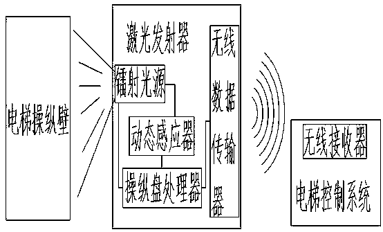
[0018] When passengers enter the elevator, the control panel processor of the laser emitter images an inductive control panel, which is projected onto the control wall of the elevator through the laser light source. The corresponding function sensing points are emitted on the elevator control wall through the laser light source. Passengers see the function buttons on the inductive control panel, and use their fingers to trigger the corresponding button leading to the 18th floor. The dynamic sensor acts on the elevator control wall and has a function sensor point leading to the 18th floor. It is converted into the execution command recognized by the elevator control system, and the information that the elevator needs to go to the 18th floor is transmitted to the elevator control system through the wireless data transmitter. After receiving the information, the elevator control system sends out an execution command. The execution command on the 18th floor closes the elevator doo...

Embodiment example 2

[0020] When the maintenance personnel enter the elevator, the maintenance personnel have the authority to maintain the elevator. The dynamic sensor will automatically identify when the maintenance personnel enter the elevator, confirm that they have the maintenance authority, and transmit the information of the maintenance authority to the laser transmitter through the wireless data transmitter. The control panel processor of the laser transmitter images an inductive control panel, which is projected onto the elevator control wall through the laser light source, and the dynamic sensor of the laser transmitter converts the corresponding functions according to the functions on the projected inductive control panel. The induction point is emitted on the elevator control wall through the laser light source. Because maintenance personnel have maintenance authority, they can trigger the dynamic sensing point through the conversion button on the induction control panel. After the dyna...


PUM


Abstract

A laser induction type elevator operating panel comprises an elevator operating wall, an elevator control system and a laser transmitter. The laser transmitter comprises a laser light source, a dynamic sensor, an operating panel processor and a wireless data transmission unit, wherein the laser light source is arranged on a transmitting head of the laser transmitter, the dynamic sensor and the operating panel processor are connected with the wireless data transmission unit and arranged in the laser transmitter, the laser induction type elevator operating panel generates operating panel images through the operating panel processor and emits the operating panel images through the laser light source, the laser induction type elevator operating panel comprises dynamic sensing points, the dynamic sensor emits the dynamic sensing points corresponding to operation function keys through the laser light source, and the wireless data transmission unit is arranged in the laser transmitter and is in wireless connection with a wireless receiver of an elevator control system. The laser induction type elevator operating panel does not need processing and assembling of an operating plate, saves manufacturing cost, and meanwhile simplifies signal transmission lines, reduces the fault rate, and is simple in operate.

Description

technical field [0001] The invention relates to an elevator control panel, in particular to a laser induction type elevator control panel. Background technique [0002] The elevator control panel is the part of the elevator operation. At present, the elevator operation panel of the traditional technology mainly includes the panel, the bottom box, the door opening and closing button, the floor indication button, the alarm bell, the intercom, the floor indication, the maintenance operation button and various control panels. and line etc. composition. The structure is complex, there are many parts and wiring, the processing and assembly are also extremely cumbersome, and many detection devices are required. It is mainly inlaid on the operating panel of the elevator. During operation, press the selected button to trigger a signal to the control board, and the control board will issue instructions to execute the selected function. Although there is also an operation panel with ...

Claims


Application Information

Patent Timeline
IPC IPC(8): B66B1/06B66B1/46
Inventor 陈志雄梁家健李晋文
Owner GUANGZHOU YONGRI ELEVATOR
Learn More