
Single-girder hanger and reach stacker

A single main beam and spreader technology, applied in the direction of load hanging components, rail system, transportation and packaging, can solve the problems of heavy mechanical structure and high bearing capacity requirements of mechanical materials, and achieve the improvement of bearing capacity and overall improvement. The effect of reducing the safety performance of the machine and reducing the load capacity requirements

Active Publication Date: 2015-05-13
SANY MARINE HEAVY IND +1
View PDF5 Cites 1 Cited by
  • Summary
  • Abstract
  • Description
  • Claims
  • Application Information

AI Technical Summary

Problems solved by technology

Since the extension of the telescopic beam of the spreader to the outside of the main beam is about 3066mm, the pressure on the end of the main beam is about 4 times the load of a single telescopic beam, which results in a heavy load on the mechanical structure and a bearing capacity for mechanical materials. The requirements are high, and this high force is even more severe under heavy load conditions, making ordinary single main girder spreaders unable to lift heavy-duty containers with a length of more than 20 ft

Method used


Image

  • Single-girder hanger and reach stacker
  • Single-girder hanger and reach stacker
  • Single-girder hanger and reach stacker

Examples


Embodiment Construction

[0034] In order to understand the above-mentioned purpose, features and advantages of the present invention more clearly, the present invention will be further described in detail below in conjunction with the accompanying drawings and specific embodiments.

[0035] In the following description, many specific details are set forth in order to fully understand the present invention. However, the present invention can also be implemented in other ways different from those described here. Therefore, the protection scope of the present invention is not limited by the specific details disclosed below. EXAMPLE LIMITATIONS.

[0036] The present invention will be further described below in conjunction with the accompanying drawings and embodiments. It should be noted that, in the case of no conflict, the embodiments of the present application and the features in the embodiments can be combined with each other.

[0037] Figure 1 to Figure 2 A schematic structural view of an embodime...


PUM


Abstract

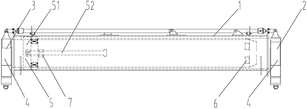
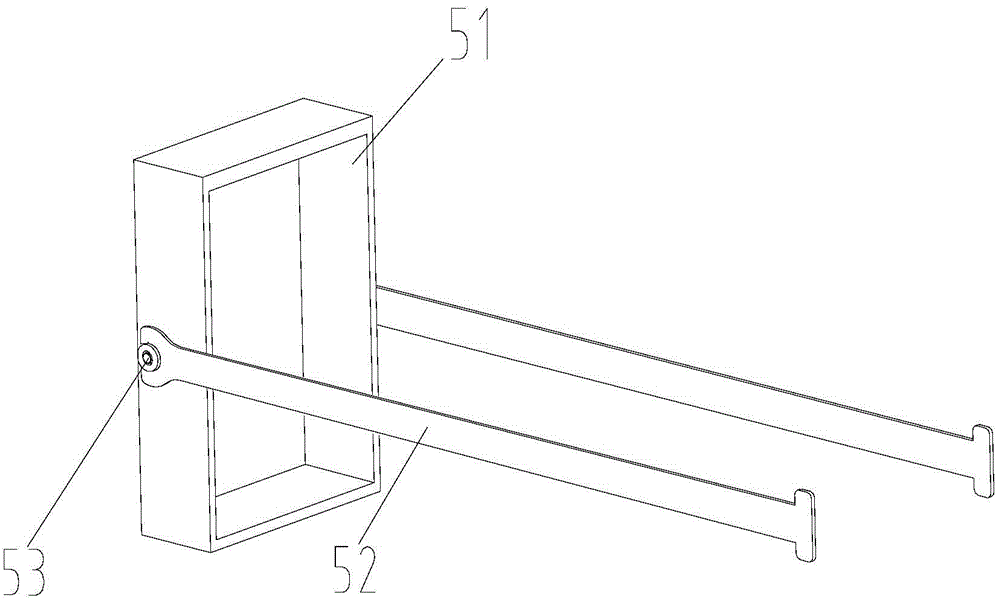
The invention provides a single main beam spreader, comprising a main beam (1); a large telescopic beam (2) and a small telescopic beam (3) located inside the main beam (1); the small telescopic beam (3) is set on the large Inside the telescopic beam (2); the beam (4), located at the free ends of the large telescopic beam (2) and the small telescopic beam (3); also includes: a follow-up support mechanism (5), one end of which is connected to the large telescopic beam (2) , the other end is set on the small telescopic beam (3), the outer wall of the follow-up support mechanism (5) is in contact with the inner surface of the main beam (1), and the inner wall of the follow-up support mechanism (5) is in contact with the outer surface of the small telescopic beam (3). connected; the first limit mechanism (6) located at the fixed end of the small telescopic beam (3); the second limit mechanism (7) located on the large telescopic beam (2). The single main girder spreader provided by the present invention realizes the follow-up support for the small telescopic beam by setting a follow-up support mechanism between the main girder and the telescopic beam, and extends the supporting arm of the two telescopic beams, thus improving the mechanical structure The stress conditions reduce the load-bearing capacity requirements of mechanical materials, improve the load-bearing capacity of the single main girder spreader, and realize the lifting operation of heavy-duty containers above 20ft.

Description

technical field [0001] The invention relates to the field of engineering machinery spreaders, in particular to a single main girder spreader and a front hanger. Background technique [0002] Heavy-duty container spreaders such as front-loading container spreaders generally adopt the structure of double main beam spreaders to meet the requirements of heavy-duty working conditions, which leads to large spreader volume, asymmetric telescopic beam structure, and increased weight of the spreader itself. And other issues. [0003] At present, the spreader of the stacker used for lifting empty containers generally adopts a single main beam structure. That is to say, the left and right telescopic beams adopt different sections and are arranged in layers in the same main beam. The advantage of this single main girder structure is that the hanging body is small in size, compact in structure and light in weight. However, due to structural and size limitations, the telescopic beam ca...

Claims


Application Information

Patent Timeline
Patent Type & Authority Patents(China)
IPC IPC(8): B66C7/10
CPCB66C1/101
Inventor 彭国成廖荣华樊伟
Owner SANY MARINE HEAVY IND
Learn More