Pumping unit
A technology of pumping units and hollow sucker rods, which is applied in the fields of exploitation fluid, wellbore/well parts, earthwork drilling and production, etc., can solve the problems of low load rate, high energy consumption, low efficiency, etc., and achieves strong practicability and structural simple effect
- Summary
- Abstract
- Description
- Claims
- Application Information
AI Technical Summary
Problems solved by technology
Method used
Image

Examples
Embodiment Construction
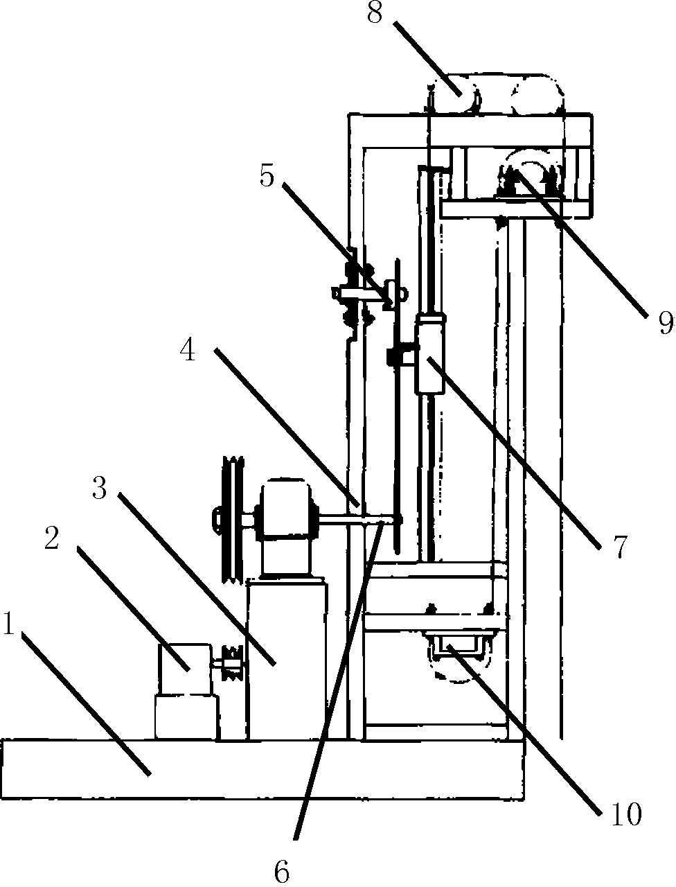
[0009] A pumping unit of the present invention comprises a machine base 1, a motor 2 is arranged on the machine base 1, the motor 2 is connected to a gearbox 3 and a gearbox 3 through a belt pulley, the machine base 1 is also provided with a sprocket seat 4, and the chain wheel seat 4 is respectively provided with upper sprocket 5 and lower sprocket 6, is connected by chain between upper and lower sprocket 6, and the connecting line between upper and lower sprocket 6 midpoints is perpendicular to the horizontal plane, and commutator 7 is connected on the chain , the base 1 is respectively provided with a chain wheel and a pulley, the upper end of the commutator 7 is connected to the solid sucker rod through the wire rope of the chain wheel, and the lower end of the commutator 7 is connected to the hollow sucker rod through the pulley; there are two upper pulleys 8, The connecting line between the middle points of the two upper pulleys 8 is parallel to the horizontal plane, whic...
PUM
 Abstract
Description
Claims
Application Information