
Installation structure of a car carbon canister

A technology of installation structure and carbon canister, which is applied to the charging system, adding non-fuel substances to fuel, engine components, etc., can solve the problems of inconvenient installation and disassembly, and achieves low requirements for processing accuracy, simple structure, and convenient production. The effect of consistency control

Active Publication Date: 2017-03-15
CHONGQING CHANGAN AUTOMOBILE CO LTD
View PDF5 Cites 0 Cited by
  • Summary
  • Abstract
  • Description
  • Claims
  • Application Information

AI Technical Summary

Problems solved by technology

However, at present, the carbon tank on the car is mostly fixed on the carbon tank bracket with bolts, which is extremely inconvenient to install and disassemble.

Method used


Image

  • Installation structure of a car carbon canister
  • Installation structure of a car carbon canister
  • Installation structure of a car carbon canister

Examples


Embodiment Construction

[0016] The present invention will be further elaborated below in conjunction with the drawings and embodiments:

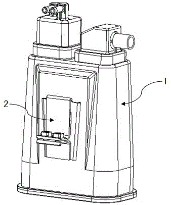
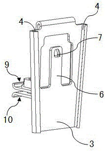
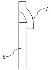
[0017] Such as figure 1 The installation structure of the car carbon canister shown includes carbon canister 1 and mounting bracket 2, see figure 2 , 5 The mounting bracket 2 includes a plate-shaped bracket body 3. The two sides of the bracket body 3 are folded toward the front to form guide grooves 4 that penetrate the entire side edges of the bracket body. The outer wall of the carbon canister 1 is gradually narrowed. Two guide rails 5 corresponding to the guide grooves 4 of the mounting bracket are provided on the outer wall of the canister 1, and the distance between the two guide rails 5 gradually narrows from top to bottom. The guide rail 5 is divided into two sections longitudinally, so that each guide rail 5 is composed of upper and lower sub-rails spaced apart. The carbon canister 1 is inserted into the guide groove 4 of the bracket body 3 through the guide r...


PUM


Abstract

The invention discloses a mounting structure of an automobile carbon tank. The mounting structure comprises the carbon tank and a mounting support. Guide grooves are formed in the edges of the two sides of the front face of a support body of the mounting support, the distance between the guide grooves in the two sides becomes narrow gradually from top to bottom, two guide rails in corresponding fit with the guide grooves of the mounting support are arranged on the outer wall of the carbon tank, the distance between the two guide rails becomes narrow gradually from top to bottom, each guide rail is divided into two sections longitudinally, and the carbon tank and the guide grooves support body are clamped and fixed through the guide rails. The mounting structure can stably and reliably fix the carbon tank, the carbon tank can be conveniently mounted and dismounted, and the requirement for mounting and dismounting operation space is low.

Description

Technical field [0001] The invention relates to an automobile fuel system component, in particular to an installation structure of an automobile carbon canister. Background technique [0002] In order to save fuel and protect the environment, a carbon canister is installed between the car’s fuel tank and the engine. The interior is filled with highly absorbent activated carbon. The excess fuel vapor in the fuel tank is no longer discharged into the atmosphere, but by a pipe. Introduce a carbon canister and use activated carbon to absorb fuel vapor. When the car is started, the valve of the carbon canister is opened at the right time to pour the absorbed fuel vapor back into the intake manifold to achieve full combustion of fuel and prevent exhaust gas from being discharged into the atmosphere. As environmental protection requirements become more and more stringent, the volume and weight of the carbon canisters on the vehicle are getting larger and heavier. Therefore, a simpler a...

Claims


Application Information

Patent Timeline
Patent Type & Authority Patents(China)
IPC IPC(8): F02M25/08
Inventor 刘华田兴德
Owner CHONGQING CHANGAN AUTOMOBILE CO LTD
Learn More