
Steam combustion-supporting burner

A combustion-supporting, burner technology, applied in the direction of solid fuel combustion, combustion methods, combustion equipment, etc., can solve the problems of wasting fuel, not in line with energy conservation and environmental protection, and achieve the effect of temperature increase

Inactive Publication Date: 2014-01-22
深圳市草木新能源有限公司
View PDF6 Cites 5 Cited by
  • Summary
  • Abstract
  • Description
  • Claims
  • Application Information

AI Technical Summary

Problems solved by technology

[0004] The temperature in the combustion pipeline of the technical solution of the above-mentioned patent generally does not exceed 300°C, and it also wastes fuel, so it does not meet the requirements of energy saving and environmental protection

Method used


Image

  • Steam combustion-supporting burner

Examples


Embodiment Construction

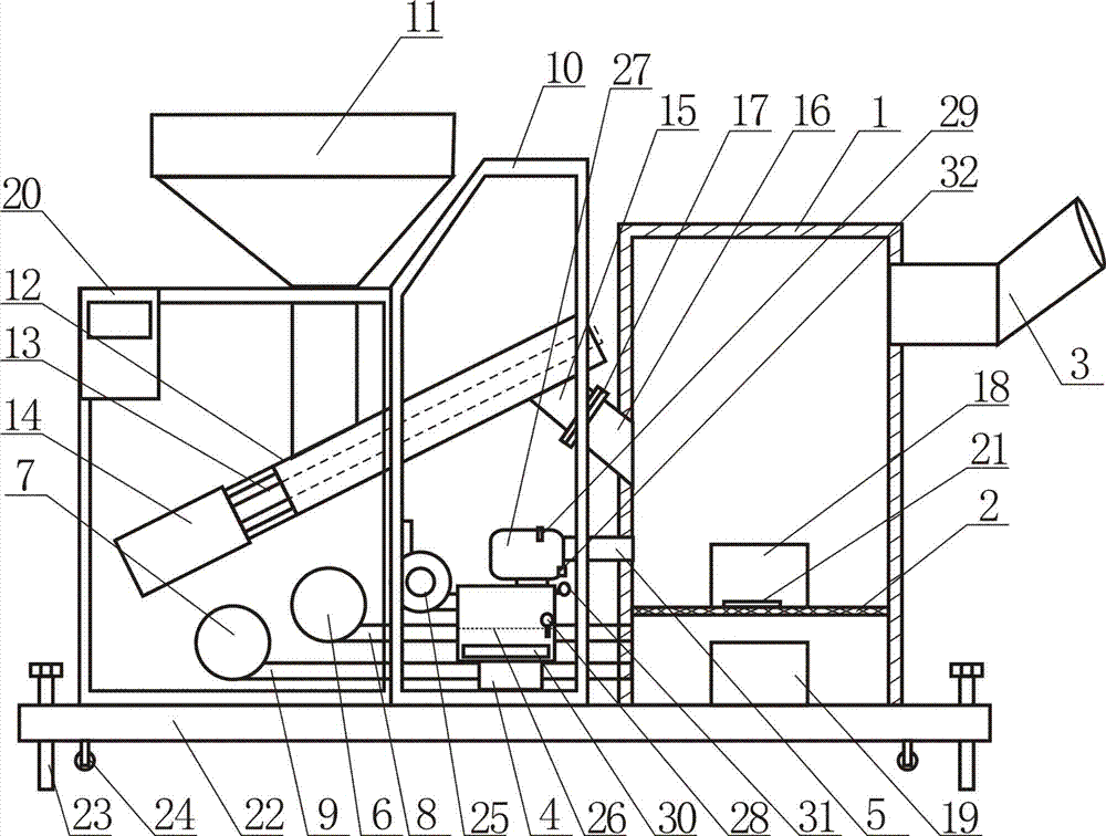
[0021] Such as figure 1 As shown, the steam combustion-supporting burner is mainly composed of a furnace body 1, a furnace plate 2, a fan, a steam generator, a smoke exhaust pipe 3 and a feeding device. The furnace plate 2 is located in the furnace body 1, and the furnace body 1 A furnace door 18 and a slag discharge door 19 are arranged on the top, and the smoke exhaust pipe 3 is arranged on the side upper part of the furnace body 1 . There are two air inlets on the furnace body 1 below the furnace tray, one is a high-pressure air inlet, and the other is a low-pressure air inlet; the fan is provided with two, a high-pressure fan 6 and a low-pressure fan 7, and the high-pressure The fan 6 communicates with the high-pressure air inlet on the furnace body 1 through the high-pressure air supply pipe 8 , and the low-pressure fan 7 communicates with the low-pressure air inlet on the furnace body 1 through the low-pressure air supply pipe 9 .

[0022] Feeding device is mainly made ...


PUM


Abstract

The invention discloses a steam combustion-supporting burner. The steam combustion-supporting burner is mainly composed of a furnace body, a furnace plate, fans, a steam generator, a smoke discharge pipe and a feeding device. The furnace plate is arranged in the furnace body. The fans are communicated with an air inlet located below the furnace plate on the furnace body through a blast pipe. The steam generator delivers generated steam into the furnace body through a steam pipe. The smoke discharge pipe is arranged on the lateral upper portion or the top of the furnace body. The fans are two in number and comprise the high pressure fan and the low pressure fan. By the adoption of the steam combustion-supporting structural form, combustible gas is blown into the smoke discharge pipe for combustion under the action of the high pressure fan, and the temperature in the smoke discharge pipe at the moment can reach over 800 DEG C while the temperature in a traditional smoke discharge pipe is only about 280 DEG C. As a result, the temperature of the steam combustion-supporting burner is greatly increased compared with that of a traditional burner, but fuel consumed by the steam combustion-supporting burner is two thirds of fuel consumed by the traditional burner, and therefore the characteristics of energy conservation and environmental protection are fully reflected.

Description

technical field [0001] The invention relates to a heating device, in particular to a burner. Background technique [0002] A burner is a general term for devices that allow fuel and air to be sprayed and mixed (or mixed and sprayed) to burn in a certain way. Burners are also called burners. According to the fuel, they can be divided into oil burners and gas burners; according to the objects of use, they can be divided into kiln burners and boiler burners; burner. Among them, oil burners are divided into light oil (such as diesel oil) and heavy oil burners (such as waste engine oil), and gas burners are divided into natural gas burners, liquefied gas burners, city gas burners, biogas burners, etc. The burner we usually refer to refers to the boiler burner. According to the structure, it is divided into: integral burner and split burner. Among them, the split burner is mainly used in industrial production. Its main feature is that the combustion system, air supply system, ...

Claims


Application Information

Patent Timeline
IPC IPC(8): F23B20/00F23L7/00
Inventor 梁万泉梁春鸿
Owner 深圳市草木新能源有限公司
Learn More