Electric synchronous loader

A synchronous loader and electric technology, applied in the field of loader, can solve the problems such as the inability to realize the no-load start of the test device to change the size and direction of the load, the limited loading stroke angle of the external force transmission line, and the large size of the loading torque. Excellent starting performance, compact structure and low power

Active Publication Date: 2014-01-22
HUNAN NANFANG AVIATION HIGH ACCURATE DRIVE
View PDF5 Cites 6 Cited by
  • Summary
  • Abstract
  • Description
  • Claims
  • Application Information

AI Technical Summary

Problems solved by technology

[0004] (1) Internal force loader: This type of loader has the advantages of simple and compact structure, good processing and assembly process, convenient maintenance, low energy consumption and low noise during operation, but loading and unloading can only be carried out when the test is stopped , and it is impossible to start the test device without load and change the magnitude and direction of the load during operation
[0005] (2) External force loader: This type of loader can be loaded by external force (mechanical force, hydraulic pressure, air pressure, etc.) during static or running, and can realize the no-load start-up of the test device, and can change the load during operation and direction, however, there are disadvantages such as limited loading stroke angle or complex connection (movable joint) of external force transmission line and too many auxiliary equipment.
[0006] (3) Moment loader: This type of loader uses meshing transmission to generate torque to load the closed system, and can be loaded and unloaded during operation. However, there are limited loading stroke angles or meshing loss and transmission noise or damage to the loading motor. Disadvantages such as high requirements and complex structure
[0007] At present, the commonly used electric synchronous loader is a torque type loader, which has low loading accuracy, poor running stability, self-loosening, too small loading torque and too large external size, allowing low-speed rotation, high production cost, and high reliability. Low-level problems need to be further improved and perfected

Method used


Image

  • Electric synchronous loader
  • Electric synchronous loader
  • Electric synchronous loader

Examples


Embodiment 1

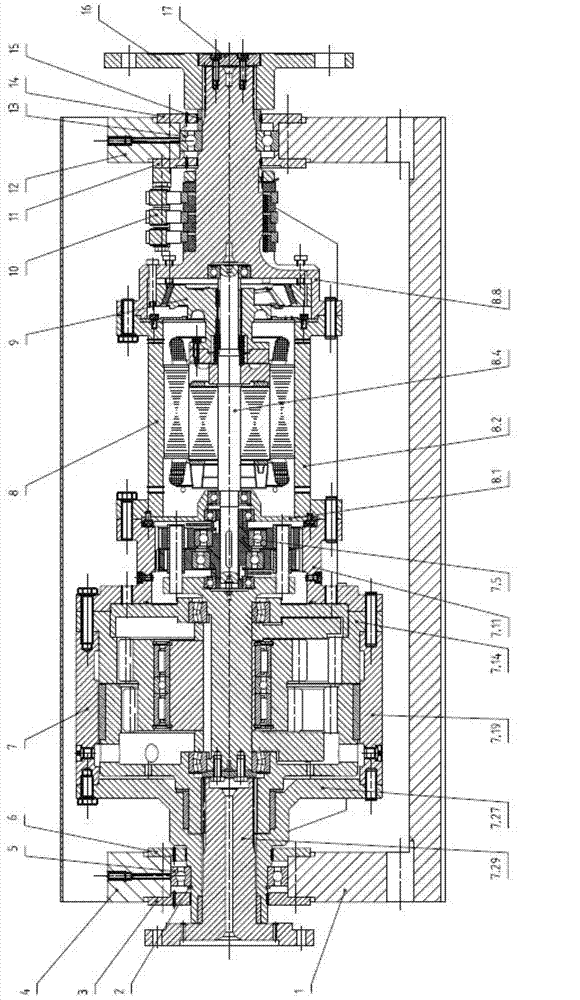
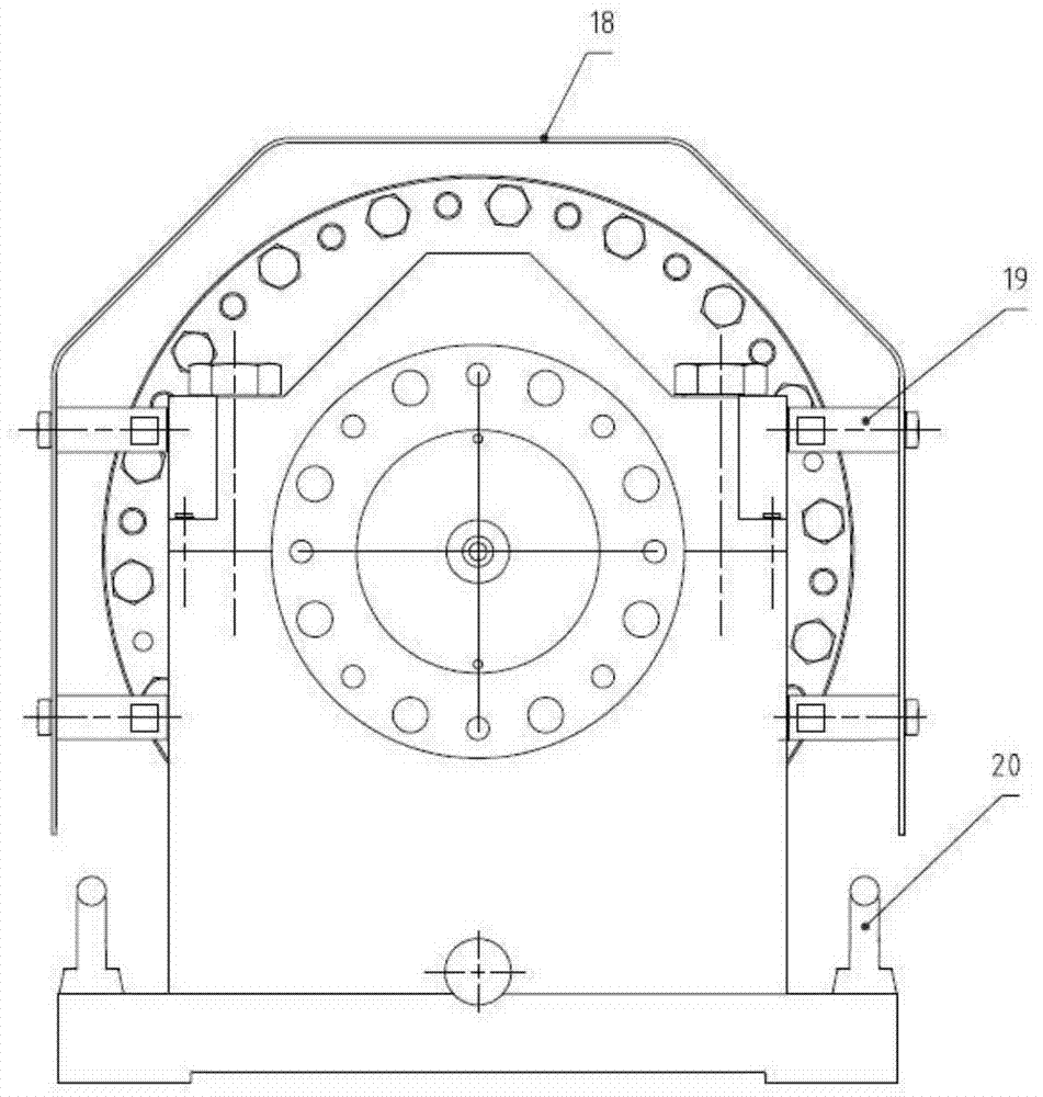
[0052] The invention provides an electric synchronous loader including a base 1, a snap ring 2, a first left end cover 3, a first bearing gland 4, a first rolling bearing 5, a first right end cover 6, a reducer 7, a loading motor 8, and a brake 9. Brake frame assembly 10, second left end cover 11, second bearing gland 12, second rolling bearing 13, second right end cover 14, bushing 15, flange 16, pressure plate 17 and cover 18, see figure 1 as well as figure 2 .

[0053] The inner holes of the first left end cap 3, the first right end cap 6, the second left end cap 11 and the second right end cap 14 are all provided with sealed rectangular grooves, and the inner cavity is provided with air holes, which are divided into two parts after integral processing. The structure is easy to install.

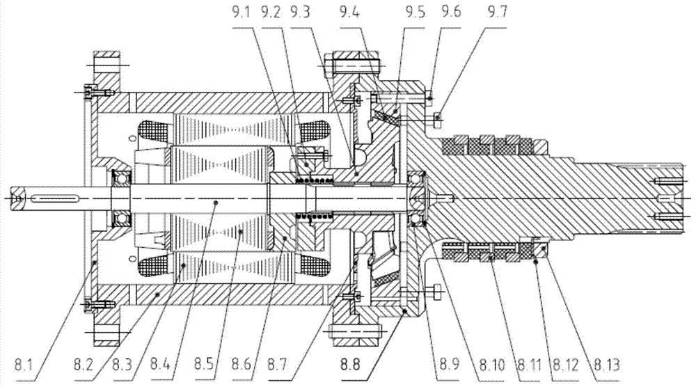
[0054] The brake 9 is installed in the inner cavity of the tail of the loading motor 8, and is integrated with the loading motor 8 to play the role of braking and load protection.

[0...


PUM


Abstract

The invention provides an electric synchronous loader which comprises a base, a speed reducer, a loading motor, a brake, a braking frame assembly and a second left end cover, wherein the speed reducer comprises a first-stage casing, a fixed inner tooth ring, a second-stage casing and an output-end supporting seat which are connected in sequence to form a rotary housing of the speed reducer; the loading motor comprises a motor housing and a rear cover which form a rotary housing of the loading motor; the brake is arranged in a tail inner cavity of the loading motor and integrally combined with the loading motor; the braking frame assembly is arranged on the second left end cover and connected with an external lead wire for introducing an external three-phase power supply. The electric synchronous loader can be used for realizing no-load starting of a test device and freely changing the size and the direction of a torque in a running process, and is infinite in loading travel angle, high in loading precision, automatic in load locking, stable in running, allowable in high-speed rotation, large in loading torque, small in external contour size, high in reliability, low in loading motor power, low in use cost and good in economy.

Description

technical field [0001] The invention relates to the field of loaders, in particular to an electric synchronous loader. Background technique [0002] In the mechanical power closed gear test device, the loader is a very important part. When used to simulate the actual working load of the tested gearbox, the performance of the loader directly affects the performance and technical and economic indicators of the mechanical power closed gear test device. Therefore, the quality of the loader determines the success or failure of the design of the mechanical power closed gear test device The essential. [0003] At present, loaders used in mechanical closure test devices are mainly divided into three categories: [0004] (1) Internal force loader: This type of loader has the advantages of simple and compact structure, good processing and assembly process, convenient maintenance, low energy consumption and low noise during operation, but loading and unloading can only be carried out...

Claims


Application Information

Patent Timeline
Patent Type & Authority Applications(China)
IPC IPC(8): G01M13/02
Inventor 李荣满张跃春谭良圆熊顺何园园
Owner HUNAN NANFANG AVIATION HIGH ACCURATE DRIVE
Why Eureka
Try Eureka