
Single-package dynamic air distributing device

A dynamic gas distribution, single-component technology, used in measuring devices, instruments, scientific instruments, etc., can solve the problems of high-sensitivity instrument inspection interference, cumbersome operation, air leakage, etc., to reduce reserves and use, meet accurate calibration, Configure flexible effects

Active Publication Date: 2014-01-22
STATE GRID CORP OF CHINA +1
View PDF9 Cites 14 Cited by
  • Summary
  • Abstract
  • Description
  • Claims
  • Application Information

AI Technical Summary

Problems solved by technology

This method requires various concentrations of raw material gas, which makes the preparation and storage of raw material gas inconvenient, and may cause waste
Moreover, it is necessary to disassemble and reinstall the gas line joint every time the raw gas is replaced, which is extremely inconvenient to operate, and multiple disassembly and assembly may easily lead to air leakage
[0006] When it is necessary to use the same gas distribution device to prepare standard gas of different components to test different gas analysis instruments, the raw material gas will also be replaced, requiring multiple disassembly and assembly of joints, resulting in cumbersome operations
[0007] The existing gas distribution device also ignores the problem of the dead volume of the gas path and the interference of the MFC leakage airflow on the output
Especially when it is necessary to output clean dilution gas for instrument zero adjustment, the leakage gas flow from the raw gas MFC or the components in the raw gas pipeline connected to the mixer will enter the dilution gas, resulting in the output of the dilution gas is not pure enough, which is harmful to The inspection of highly sensitive instruments causes a lot of interference

Method used


Image

  • Single-package dynamic air distributing device
  • Single-package dynamic air distributing device

Examples


Embodiment 1

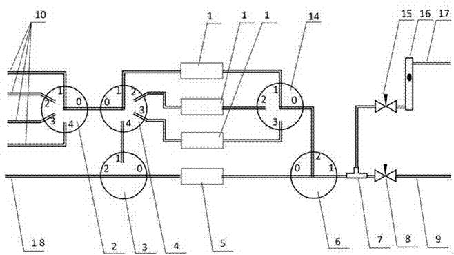
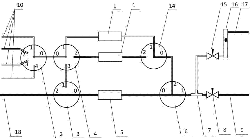
[0029] Such as figure 1 As shown, a single-component dynamic gas distribution device includes a feed gas mass flow controller 1, a dilution gas mass flow controller 5, a mixer 6, a feed gas access ball valve 4, and a feed gas output ball valve 14: wherein, the mixing The device 6 includes two inlets and an outlet for outputting standard gas; the inlet of the dilution gas mass flow controller 5 is connected to the dilution gas inlet 18, and the dilution gas is inserted, and the outlet is connected to an inlet of the mixer 6 to form a dilution gas path; raw material The number of gas mass flow controllers 1 is at least 2, and the measuring range increases proportionally, and the common ratio of the proportional growth is not less than 5, that is, if two raw gas mass flow controllers 1 are used, the second raw gas mass flow controller The measuring range of the first device 1 is n times of the first one; if three are used, the measuring range of the third one is n times of the se...

Embodiment 2

[0032] On the basis of Embodiment 1, the single-component dynamic gas distribution device in this embodiment also includes a diluent gas access ball valve 3, and the diluent gas access ball valve 3 is an L-shaped three-way ball valve, including two inlets and a outlet, the outlet of which is connected to the inlet of the dilution gas mass flow controller 5, and one of its inlets is connected to the dilution gas; in addition, the number of outlets of the feed gas connected to the ball valve 4 is greater than the number of feed gas mass flow controllers 1, so that the feed gas The outlet of the ball valve 4 is connected to the outlet of the raw material gas mass flow controller 1, and there is one outlet left, which is connected to the other inlet of the L-shaped three-way ball valve. The L-type three-way ball valve is used to select the gas flowing through the dilution gas mass flow controller 5. The L-type three-way ball valve 3 is switched to No. 2 port, and when the raw mater...

Embodiment 3

[0034] Such as figure 1 As shown, the difference between this embodiment and Embodiment 1 or Embodiment 2 is that the quantity of the above-mentioned feed gas mass flow controllers 1 is three, wherein the range of the second feed gas mass flow controller 1 is the first feed gas mass flow controller 1 Gas mass flow controller 1 is 10 times, the third raw gas mass flow controller 1 is 10 times that of the second raw gas mass flow controller 1, that is, the measuring range increases by a common ratio of 10, and the dilution gas mass flow controller 5 is a mass flow controller with a large range, and its measuring range is generally more than twice the largest measuring range of the raw material gas mass flow controller 1, specifically: the measuring ranges of the three raw material gas mass flow controllers 1 are: 5mL / min, control flow range (0.5-5) mL / min; 50mL / min, control flow range (5-50) mL / min; 500mL / min, control flow range (50-500) mL / min; dilution gas mass flow rate The...


PUM


Abstract

The invention discloses a single-package dynamic air distributing device which comprises feed gas mass flow controllers, a diluent gas mass flow controller and a mixer. An outlet of the diluent gas mass flow controller is connected with an inlet of the mixer, and the single-package dynamic air distributing device further comprises a feed gas input ball valve and a feed gas output ball valve. The feed gas input ball valve and the feed gas output ball valve both are multi-way ball valves, the number of the feed gas mass flow controllers is at least two, the measuring ranges of the feed gas mass flow controllers increase in equal ratio, the common ratio of equal ratio is not smaller than 5, feed gas is input to the feed gas mass flow controllers through the feed gas input ball valve, and the feed gas mass flow controllers are connected with the inlet of the mixer through the feed gas output ball valve. According to the single-package dynamic air distributing device, a wide dilution ratio range is provided, feed gas of one concentration can be used for preparing standard gas meeting requirements of most instruments to be detected, storage and use of the feed gas are reduced, a connector does not need to be mounted and dismounted, airflow leakage and diffusion interference can be avoided, and the single-package dynamic air distributing device has the advantages of being convenient to use, flexible in allocation, and the like.

Description

technical field [0001] The invention relates to the technical field of gas distribution devices, in particular to a single-component dynamic gas distribution device. Background technique [0002] When calibrating, calibrating and inspecting gas analyzers, it is necessary to use standard gases of various components and concentrations according to the specific parameters of the instrument to be tested. The standard gases are usually prepared by dynamic gas distribution method. The serial dilution method is an important method in the dynamic gas distribution method. Its principle is to divide the known concentration of raw gas (which can be one or a variety of non-reactive species) and dilution gas (also known as zero gas) respectively. A new standard gas is prepared by mixing and diluting at a certain flow rate. The concentration of each component of the output standard gas can be calculated by multiplying the concentration of the raw material gas by the dilution ratio (the di...

Claims


Application Information

Patent Timeline
Patent Type & Authority Applications(China)
IPC IPC(8): G01N1/38G01N33/00
Inventor 张力王志高王杰
Owner STATE GRID CORP OF CHINA
Learn More