Current transducer for measuring a current

A current converter and current technology, applied in the direction of measuring current/voltage, measuring electrical variables, measuring electricity, etc., can solve problems such as machine damage and achieve the effect of low sensitivity

Inactive Publication Date: 2014-01-22
SENIS
View PDF0 Cites 22 Cited by
  • Summary
  • Abstract
  • Description
  • Claims
  • Application Information

AI Technical Summary

Problems solved by technology

In the event of a short circuit there is a high risk of the machine being damaged

Method used


Image

  • Current transducer for measuring a current
  • Current transducer for measuring a current
  • Current transducer for measuring a current

Examples


Embodiment Construction

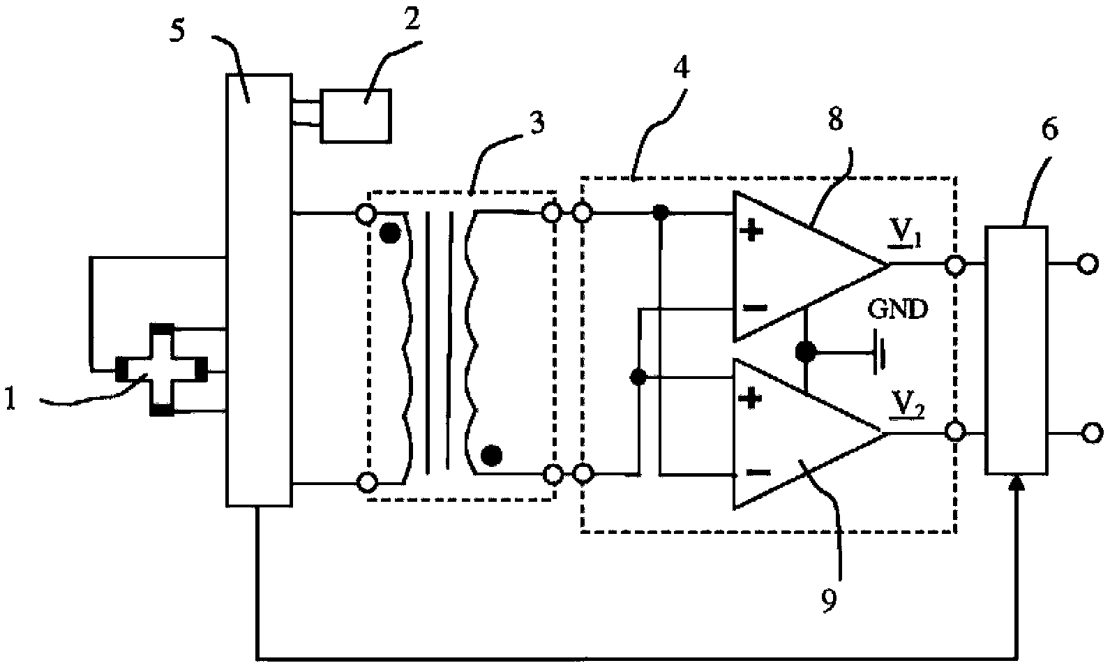
[0071] figure 1 A schematic diagram of a first embodiment of a magnetic converter according to the invention is shown. A magnetic transducer includes a magnetic field sensor and circuitry to operate the magnetic field sensor. In this first embodiment, the magnetic field sensor is a Hall element 1 . The circuit includes a first current source 2 for supplying supply current to the Hall element 1 , a transformer 3 , a preamplifier 4 , a logic module 5 and a phase sensitive detector 6 . The transformer 3 has a primary winding including two input terminals and a secondary winding including two output terminals. The preamplifier 4 is a fully differential amplifier having two input terminals and two output terminals. A first output terminal of the transformer 3 is coupled to a first input terminal of the preamplifier 4 and a second output terminal of the transformer 3 is coupled to a second input terminal of the preamplifier 4 .

[0072] The Hall element is a magnetic field senso...


PUM


Abstract

The invention concerns a current transducer for measuring a current flowing through a cable, comprising at least one magnetic field sensor and an electronic circuit. The current transducer comprises a head (40) with at least two ferromagnetic cores (46) optimized to reduce the effects of external magnetic fields. The current transducer optionally comprises a magnetic transducer comprising a magnetic field sensor and an electronic circuit. The electronic circuit comprises at least one current source (2), a transformer (3), a fully differential preamplifier (4) coupled to the transformer (3), a phase sensitive detector (6) coupled to the preamplifier (4) and a logic block (5, 5a) configured to operate the magnetic field sensor(s) to provide an AC output voltage. The magnetic field sensor(s) is preferably either a Hall element (1) or an AMR sensor (19) or a flux-gate sensor.

Description

technical field [0001] The invention relates to a current transformer for measuring current flowing through an electrical cable. Background technique [0002] An important application of magnetic transducers is non-intrusive current measurement by measuring the magnetic field generated by the current (without damaging the cables carrying the current). A convenient way of performing such current measurements is by means of current transformers comprising so-called clamp-on current transformers. Current transducers capable of measuring DC and AC current typically include a combination of a ferromagnetic core surrounding a cable carrying the current and a magnetic transducer. The minimum value of current that can be measured by the associated magnetic field depends largely on the inherent noise of the magnetic transducer and the sensitivity of the measurement system to external magnetic fields. The accuracy of clamp-on ammeters is also limited by the dependence of the measure...

Claims


Application Information

Patent Timeline
Patent Type & Authority Applications(China)
IPC IPC(8): G01R15/18G01R19/00
CPCG01R33/04G01R15/20G01R33/07G01R31/025G01R33/096G01R31/52
Inventor 拉迪沃耶·波波维奇马里安·布拉戈耶维奇萨沙·迪米特里耶维奇卡伦·路易斯·劳伊恩·詹姆斯·沃克
Owner SENIS
Why Eureka
Try Eureka