

Piece type transformation method of transformer tubular cooling system
A cooling system and transformer technology, applied in the field of transformers, can solve the problems of high power consumption and noise, and achieve the effects of prolonging service life, reducing operating noise, and reducing operation and maintenance costs
- Summary
- Abstract
- Description
- Claims
- Application Information
AI Technical Summary
Problems solved by technology
Method used
Image

Examples
Embodiment Construction
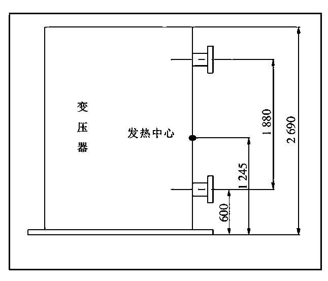
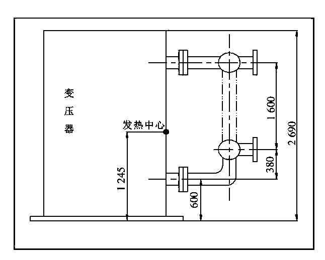
[0010] Before the renovation, the cooling method of the original transformer was radiator plus air cooling, and there are 16 fans with high speed and loud noise. The transformer no-load loss: 43.00kW, load loss: 154.09kW. The transformer adopts tube radiator and is air-cooled. The relevant data of the tube radiator are as follows: the installation center distance of the tube radiator is 1880㎜; the number of heat pipes in each group: 120; the number of tube radiator groups: 8 groups. There are 16 fans, model BF-4Q4, 250W, 1 450r / min. After calculation, the air-cooled effective heat dissipation area of a single tube radiator is 31.00㎡, and the total effective air-cooled heat dissipation area is: 31.00×8=248.0㎡. There are 16 fan motors with a rated power of 0.25kW. The purpose of the transformation is to change the tube air cooling to the plate self cooling.
[0011] Cause analysis of unsatisfactory heat dissipation of transformer
[0012] Whether the self-cooling effect...
PUM
 Abstract
Description
Claims
Application Information