
Variable capacitance type capacitor

A variable type, capacitor technology, used in variable capacitors, capacitors, tubular capacitors, etc., can solve the problems of time-consuming, poor productivity, and difficulty in miniaturizing components

Active Publication Date: 2014-01-22
WACOM CO LTD
View PDF7 Cites 4 Cited by
  • Summary
  • Abstract
  • Description
  • Claims
  • Application Information

AI Technical Summary

Problems solved by technology

[0010] However, in the capacitance variable capacitor for the position indicator of Patent Document 1, a plurality of component groups are arranged in the direction of the applied pressure, and the second conductor is elastically displaced according to the applied pressure. Therefore, the component groups are assembled in advance. In the case of a modular component, it is necessary to accommodate the component in a predetermined case member, and it is difficult to miniaturize the modular component
Therefore, if it is installed as a modular part, there is a problem that it becomes an obstacle when the pen-shaped position indicator is refined.
In addition, the thinner the pen-shaped position indicator is, the more difficult it is to secure the opposing area between the second conductor and the other end surface of the dielectric.
[0011] In addition, when a predetermined component group is assembled to produce a modular component, the assembly takes time
Therefore, it takes time for the operator to assemble the modular parts, and then combine them with other parts and arrange them in the casing, and there is also a problem of poor productivity.

Method used


Image

  • Variable capacitance type capacitor
  • Variable capacitance type capacitor
  • Variable capacitance type capacitor

Examples


no. 1 Embodiment approach

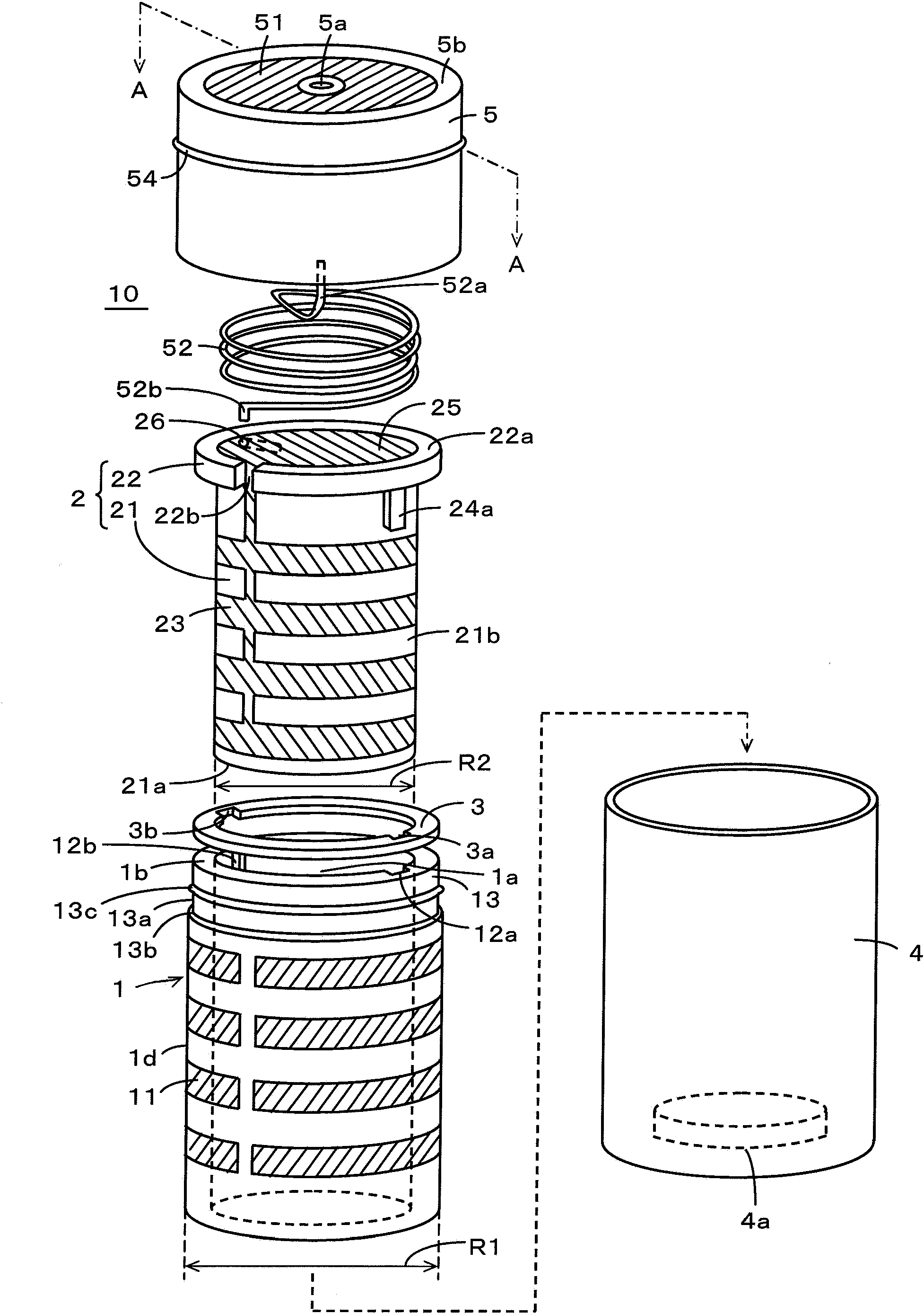
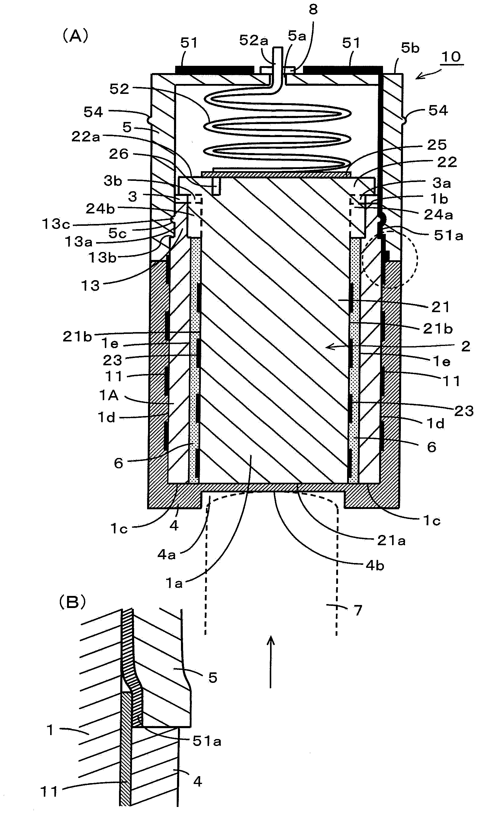
[0041] figure 1 It is an exploded perspective view showing the overall structure of the first embodiment of the capacitance variable capacitor of the present invention. also, figure 2 (A) is a longitudinal sectional view of the first embodiment of the capacitance variable capacitor of the present invention ( figure 1 A-A line sectional view in). also, figure 2 (B) is figure 2 An enlarged view of a portion surrounded by a circle in (A).

[0042] figure 1 and figure 2 As shown in (A), the capacitance variable capacitor 10 of the first embodiment includes an outer member 1 formed of a cylinder having a hollow space 1a, and an inner member 2 housed in the hollow space 1a of the outer member 1. , A buffer member 3 for buffering, a protective case member 4 , and a connection member 5 for electrode lead-out provided between the outer member 1 and the inner member 2 .

[0043] The outer member 1 is made of a dielectric material having a predetermined dielectric constant such...

no. 2 Embodiment approach

[0182] In the first embodiment described above, the protective case member 4 is used to seal the end surface 21 a side of the columnar portion 21 of the inner member 2 and the end surface 1 c side of the outer member 1 . A thin portion 4b is provided at the bottom of the protective case member 4, and the columnar portion 21 of the inner member 2 is pressed and displaced in the central axis direction by a pressing member through the thin portion 4b. However, the protective case member can be omitted by providing the outer member as the bottomed hollow outer member 1A.

[0183] In addition, in the first embodiment described above, when forming the position indicator 100 , in order to connect to the rod-shaped capacitor 120 , the connection adapter 140 is used. However, the connection member 5 of the capacitance variable capacitor may also be configured to function as the connection adapter 140 for connecting to the rod-shaped capacitor 120 .

[0184] The capacitance variable ca...


PUM


Abstract

A variable capacitance type capacitor is provided, which has a simple construction, can be easily housed in a thin type casing such as that of a position indicator or the like, and can be readily put into mass production. The variable capacitance type capacitor includes an inside member and an outside member including a space for housing the inside member. The inside member has a columnar shape, and a first conductor pattern is formed on a circumferential surface thereof. The outside member has a predetermined dielectric constant, and a second conductor pattern is formed on an outer circumferential surface thereof so as to oppose the first conductor pattern formed on the inside member. The inside member housed in the space of the outside member is displaced relative to the outside member in a direction of a central axis of the inside member in response to an externally applied force, and an opposed area between the first conductor pattern and the second conductor pattern changes to thereby form a capacitance corresponding to the externally applied force between the first electrode and the second electrode.

Description

technical field [0001] The present invention relates to a capacitance variable capacitor that detects pressure applied from the outside as a change in electrostatic capacitance. Background technique [0002] As an example of a position input device used as an input device such as a personal computer, for example, the following devices are known, which include: a position indicator having a pen shape and having a pen pressure detection unit; An input surface for inputting instruction operations, characters, images, and the like. [0003] In addition, conventionally, a capacitance-variable capacitor described in Patent Document 1 (Japanese Patent Laid-Open No. 4-96212) has been used for a pen pressure detection unit of a position indicator. In the capacitance variable capacitor described in Patent Document 1, as a structural component housed in an elongated cylindrical frame, there is a combination of a first conductor mounted on one end surface of a cylindrical dielectric an...

Claims


Application Information

Patent Timeline
Patent Type & Authority Applications(China)
IPC IPC(8): H01G5/14G06F3/03
CPCG01D5/2417H01G4/28H01G5/0136G06F3/03545G01D5/2412H01G5/14G06F3/03H01G5/013
Inventor 小幡政行
Owner WACOM CO LTD
Learn More