Direct lead wire grounding wire mounting and dismounting device

A wire grounding and lead wire technology is applied in the field of direct lead wire ground wire assembly and disassembly devices, which can solve the hidden dangers of knife gate porcelain bottles, difficulty in assembling and dismantling the ground wire, and damage to operators, so as to eliminate potential safety hazards, ensure reliable connection, and reduce errors. effect of operation

Inactive Publication Date: 2014-01-22
STATE GRID CORP OF CHINA +1
View PDF8 Cites 14 Cited by
  • Summary
  • Abstract
  • Description
  • Claims
  • Application Information

AI Technical Summary

Problems solved by technology

[0003] At present, it is a frequent operation to install and disassemble the grounding wire in the switching operation of conventional substations. The operation of installing and disassembling the grounding wire also has certain risks. There may be a safety hazard that the ground wire may fall off and injure the operator and the porcelain bottle of the knife switch.
Due to the equipment itself and the layout of some substations, the lead wires for installing the ground wires have vertical and horizontal planes, which makes it more difficult to install and disassemble the ground wires. It often requires two people to cooperate with each other to complete this operation. The assembly and disassembly of the grounding wire increases the potential safety hazard of accidentally touching the live equipment and causing the live wire to hang on the grounding wire, and the problem that the grounding wire falls off due to the wrong cooperation of two people.

Method used


Image

  • Direct lead wire grounding wire mounting and dismounting device
  • Direct lead wire grounding wire mounting and dismounting device
  • Direct lead wire grounding wire mounting and dismounting device

Examples


Embodiment Construction

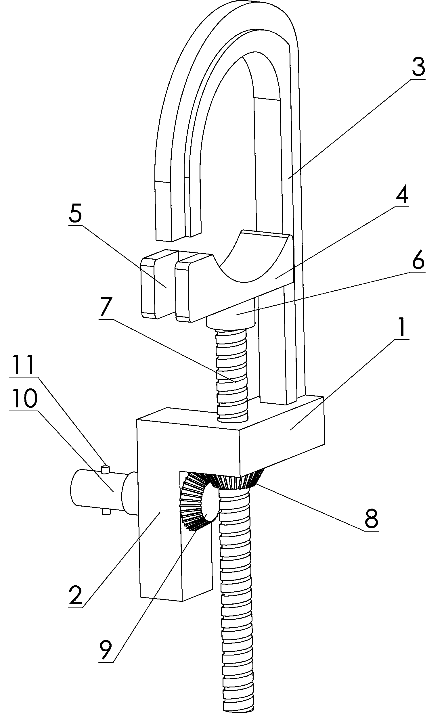
[0015] as attached Figure 1-3 As shown, the present invention consists of a lead clamping device and a remote operating lever; the lead clamping device includes a base 1, an L-shaped conjoined seat 2 arranged at the lower end of the base 1, and an upper The hook 3, the lower locking device inserted in the longitudinal through hole of the base 1, and the disguised transmission device inserted in the transverse through hole of the L-shaped conjoined seat 2; the lower locking device includes a longitudinal screw 7, arranged in the longitudinal The lower hook 4 at the upper end of the screw rod 7 and the longitudinal bevel gear 8 threadedly connected with the longitudinal screw rod 7, the lower end of the lower hook 4 is fixedly provided with a bearing seat 6, and the upper end of the longitudinal screw rod 7 is inserted into the bearing seat 6 In the shaft hole, the lower end of the longitudinal screw 7 is inserted into the longitudinal through hole of the base 1; the phase-chan...


PUM


Abstract

The invention relates to a direct lead wire grounding wire mounting and dismounting device, which consists of a lead wire clamping device and a remote operation rod, wherein the remote operation rod consists of a telescopic rod and a center position limiting hole, the center position limiting hole is formed at the top end of the telescopic rod and is matched with the tail end part of a transverse transmission rod, and the side wall of the center position limiting hole is provided with a position limiting groove. When the direct lead wire grounding wire mounting and dismounting device is used, the electric power accident can be effectively avoided, the potential safety hazard is eliminated, meanwhile, the work can be completed only by one worker, meanwhile, the efficiency is greatly improved, and the misoperation phenomenon is reduced. When a switch pull-rod is used for mounting and dismounting a grounding wire on a direct lead wire, the switch pull-rod needs to incline to a certain angle from a ground wire head, so the risk of operator injury or disconnecting link porcelain bottle damage through crashing due to the disconnection between the ground wire head and the switch pull-rod can easily occur. The direct lead wire grounding wire mounting and dismounting device has the advantages that the connection between a special switch pull-rod and the ground wire head is reliable, and under the main situation of advocating personnel reduction and efficiency enhancement, the operation time is shortened.

Description

[0001] technical field [0002] The invention relates to a device for installing and disassembling straight lead wires and grounding wires. Background technique [0003] At present, it is a frequent operation to install and disassemble the grounding wire in the conventional substation switching operation, and there is also a certain risk in the operation of installing and disassembling the grounding wire. There may be a safety hazard that the ground wire may fall off and injure the operator and the porcelain bottle of the knife switch. Due to the equipment itself and the layout of some substations, the lead wires for installing the ground wires have vertical and horizontal planes, which makes it more difficult to install and disassemble the ground wires. It often requires two people to cooperate with each other to complete this operation. Assembling and disassembling the grounding wire increases the potential safety hazard of accidentally touching the live equipment and caus...

Claims


Application Information

Patent Timeline
Patent Type & Authority Applications(China)
IPC IPC(8): H01R11/15H01R43/00
Inventor 王乾万强赵志峰李信史文丽刘国平黄朝晖王少博张兰钦杜洁董江涛刘卉王云千马清宋占平孙昊张弛刘霄赵昆李佳琪李莉左静美杨华仝志强
Owner STATE GRID CORP OF CHINA
Why Eureka
Try Eureka